background image

October 2012

2-83

ColorQube 8570/8870 Service Manual

99,042 ~ 99,051

Fault Messages and Codes

Xerox Internal Use Only - Revised, 3rd Revision

99,042 ~ 99,051 PEST - Power Supply Faults

A Power Supply error has occurred. The following troubleshooting procedure applies to these 
errors.

Initial Actions

Reboot the printer and verify the error persists.

Check the component power connections and harness condition.

If the problem persists, perform the following procedure.

Troubleshooting Reference

Applicable Parts (Chapter 5 - Parts List)

Printhead Assembly, 

PL 2.1 Item 3

Electronics Module, 

PL 5.1 Item 1

Main Controller Board, 

PL 5.1 Item 7

Wiring and Plug/Jack Reference (Chapter 7 - Wiring Data)

Figure 8

, Main Controller Board P/J Locations

Procedure

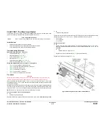
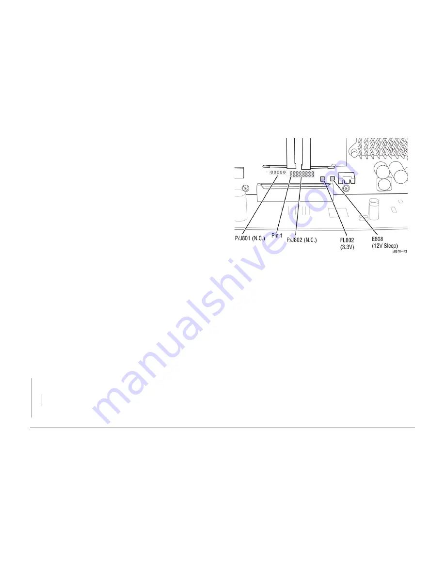
Test the Power Supply. Test voltages at 

 P/J802

 (see 

Figure 1

).

+1.0 V (pin 10)

+1.2 V (pin 6)

+1.8 V (pin 8)

+2.5 V (pin 14)

+ 3.3 V (Ferrite FL802, see 

Figure 1

)

Are measurements /- 5%?
Y

N
Unplug the Printhead gray data cable and remeasure voltages. Are the voltages within 
specification (+/- 5%)?
Y

N
Replace the Electronics Module (

REP 5.1

).

Replace the Printhead (

REP 2.3

).

Replace the Main Controller Board (

REP 5.6

) (Electronics Module).

Figure 1 Test Points on the Main Controller Board

Table 1 Applicable Fault Codes

99,042

PEST - Power 1.0 Over Limit

99,043

PEST - Power 1.0 Under Limit

99,044

PEST - Power 1.2 Over Limit

99,045

PEST - Power 1.2 Under Limit

99,046

PEST - Power 1.8 Over Limit

99,047

PEST - Power 1.8 Under Limit

99,048

PEST - Power 2.5 Over Limit

99,049

PEST - Power 2.5 Under Limit

99,050

PEST - Power 3.3 Over Limit

99,051

PEST - Power 3.3 Under Limit

Содержание COLORQUBE 8570

Страница 1: ...ColorQube 8570 8870 Printer ColorQube 8570 8870 Service Manual Xerox Internal Use Only...

Страница 2: ......

Страница 3: ...ublished rights reserved under the copyright laws of the United States Contents of this publication may not be reproduced in any form without permission of Xerox Corporation Copyright protection claim...

Страница 4: ...October 2012 ColorQube 8570 8870 Service Manual Revised 3rd Revision Xerox Internal Use Only Introduction...

Страница 5: ...the Printer v Electrostatic Discharge Precautions vii Regulatory Requirements vii Translation of Warnings viii ColorQube 8570 8870 Overview ix Printer Configurations x Parts of the Printer x Printer O...

Страница 6: ...October 2012 ii ColorQube 8570 8870 Service Manual Revised 3rd Revision Xerox Internal Use Only Introduction...

Страница 7: ...Repairs Repairs include procedures for removal and replacement of spare parts listed in the Parts List Use the repair procedures for the correct order of removal and replacement for warnings cau tion...

Страница 8: ...place objects on the power cord Do not block the ventilation openings These openings are provided to prevent overheat ing of the printer Do not drop paper clips or staples into the printer The power...

Страница 9: ...he Xerox warranty service agreement or Total Satisfaction Guarantee Symbols Used on the Printer Warnings Cautions and Notes Be aware of all symbols and terms when they are used and always read Note Ca...

Страница 10: ...ngers in the printer Use caution to avoid personal injury Figure 2 Pinch Injury Symbol Use caution or draws attention to a particular component Figure 3 Use Caution Symbol Line Voltage present on the...

Страница 11: ...B s Regulatory Requirements Xerox has tested this printer to electromagnetic emission and immunity standards These stan dards are designed to mitigate interference caused or received by this printer i...

Страница 12: ...persone per sollevarlo o rimuoverlo Tentare di rimuovere o sollevare questo componente con meno di X pesone pu provocare gravi ferite VORSICHT Versuchen Sie keinesfalls die folgende Komponente mit we...

Страница 13: ...c le contact principal activ ou avec l ali mentation lectrique appliqu e la machine Certains l ments de la machine compor tent des tensions lectriques dangereuses qui peuvent causer un choc lectrique...

Страница 14: ...5 250 sheet Optional Optional Optional Optional Duplex Optional Standard Standard Standard Hard Disk Drive Optional Optional Optional Optional Printer Stand Optional Optional Optional Optional Wireles...

Страница 15: ...M and NVRAM The optional Hard Disk Drive if installed is mounted on the rear panel When replacing an Electronics Module transfer the following components to the new Electron ics Module RAM Configurati...

Страница 16: ...ed in the printer Figure 1 RAM Optional 525 Sheet Feeder Tray 3 4 or 5 The Optional 525 Sheet Feeder increases the input capacity of the printer and can be attached to the printer underneath Tray 2 Th...

Страница 17: ...ntrol Panel menu items 9 Power Saver Button Indicator Light Brings the printer out of or puts the printer into Power Saver mode On Steady Printer can be put in Power Saver mode at this time Off Printe...

Страница 18: ...Revision Xerox Internal Use Only Introduction Menu Map Figure 1 and Figure 2 illustrate the Menu Map for the ColorQube 8570 8870 The Menu Map can be accessed through the Control Panel Control Panel Me...

Страница 19: ...The ColorQube 8570 8870 printer uses a new formulation of Ink having unique properties The Ink Loader on these products is keyed to accept this Ink shape only The use of Ink not specifi cally designed...

Страница 20: ...k stick types or SKU s meant for particular geographic regions can be determined by looking at size of the ink stick and the bottom of the ink stick Compare the letter pattern in Table 2 and Table 3 f...

Страница 21: ...ix transfer from oil coated Drum Color Medium Cyan Magenta Yellow and Black Ink Sticks each shape coded the printer uses the subtractive color system to produce the colors Red Green and Blue Color Man...

Страница 22: ...ting 250 W Idle 104 W Power Saver 45 W 38 W 110 41 W 220 In rush Current Less than 12A 110 Less than 6A 220 Leakage Current Less than 3 5 mA Table 4 Environmental Specifications Characteristic Specifi...

Страница 23: ...e review the following storage guidelines with the customer Store paper in dark cool relatively dry locations Most paper items are susceptible to damage from ultraviolet UV and visible light UV radiat...

Страница 24: ...any ink due to that it might not be able to purge the Printhead if nec essary on exit from Power Saver mode A static Tray is missing Standby Mode The printer can be set up to go into Standby mode per...

Страница 25: ...following minimum clearances Figure 1 Clearance Specifications Table 1 Print Engine Dimensions 8570N DN DT 8870DN Width 16 0 in 40 6 cm 16 0 in 40 6 cm Depth 20 5 in 52 1 cm 20 5 in 52 1 cm Height 14...

Страница 26: ...computer on a Windows or Macin tosh Startup Page Contains basic printer configuration and network information The Startup Page prints during the startup sequence when enabled or if the printer detects...

Страница 27: ...alk conditions at startup AppleTalk Runtime Log Prints a report containing AppleTalk recent runtime conditions Troubleshooting Control Panel Menu Troubleshooting Service Tools Printer Status Page Prov...

Страница 28: ...ar and the printer prints 3 Oil Bar Chase pages Purge Efficiency Provides diagnostic image for evaluating jetting performance of the Printhead after eliminate light stripes and the printer prints 1 Pu...

Страница 29: ...achine converts AC power from power source to DC power DNS Domain Name System DDNS Dynamic Domain Name System DDR2 DIMM Double Data Rate Dual In Line Memory Module DHCP Dynamic Host Configuration Prot...

Страница 30: ...l Network Area LBS Pounds Table 1 Acronyms and Abbreviations Acronyms Abbreviations Description LCD Liquid Crystal Display LE Leading Edge LED Light Emitting Diode LEF Long Edge Feed L H Left Hand LJ...

Страница 31: ...line Memory Module used to increase printing capacity Simplex Single sided copies Table 1 Acronyms and Abbreviations Acronyms Abbreviations Description SKU Stock Keeping Unit SLP Service Location Prot...

Страница 32: ...October 2012 xxviii ColorQube 8570 8870 Service Manual Acronyms and Abbreviations Revised 3rd Revision Xerox Internal Use Only Introduction...

Страница 33: ...Service Manual Service Call Procedures Xerox Internal Use Only Revised 3rd Revision 1 Service Call Procedures Service Call Procedures 1 3 Initial Actions 1 6 Routine Maintenance Activities 1 6 Cleani...

Страница 34: ...October 2012 1 2 ColorQube 8570 8870 Service Manual Revised 3rd Revision Xerox Internal Use Only Service Call Procedures...

Страница 35: ...he Wiring Diagrams and Plug Jack Locator in Chapter 7 Wiring Data to locate test points Take voltage readings as instructed in the troubleshooting procedure 4 Correct the problem Use the Parts List in...

Страница 36: ...ools Printer Status Page 3 The Printer Status page and Light Stripes Test pages are printed The Jam History and Fault History are listed on the second page of the report Example Figure 1 Jam History a...

Страница 37: ...rs Phillips 2 and 1 5 0 x 75 mm 3 0 x 75 mm 6 0 x 100 mm Serial Adapter Cable 600T80374 Small Channel Lock Pliers Torque Screw Driver Required for this printer P N 003082700 Torx Driver Bits T5 T8 T10...

Страница 38: ...ify this information into categories Information that is related to the problem that caused the service call Information that is related to secondary problems Information that does not require action...

Страница 39: ...Figure 2 Removing the Waste Tray NOTE The Waste Tray may be locked if the printer is in a warm up cycle or if the ink is cooling down following the Eliminate Light Stripes troubleshooting routine If...

Страница 40: ...menu Procedure CAUTION Do not use any solvents unless directed to do so in this manual General Cleaning Use a dry lint free cloth or a lint free cloth moistened with water for all cleaning unless dir...

Страница 41: ...he printer comes up from a Cold state less than 90 degrees Celsius The Printhead cleaning cycle consists of the following opera tions applying pressure to the reservoir of the Printhead to push ink ou...

Страница 42: ...he Retard Roller Figure 4 Cleaning the Retard Roller 3 Close the affected tray NOTE Clear packaging tape can also be used to clean the Retard Roller 1 Remove the affected Tray 2 Peel off a strip of ta...

Страница 43: ...embly 3 Close Tray 2 Clean the Drum Temperature Sensor CAUTION Cleaning under the Sensor is not recommended Only perform this procedure when there is an issue with Drum temperatures too hot or too col...

Страница 44: ...re 8 Opening the Exit Cover 2 Lift the Paper Guide toward the front of the printer Figure 9 Opening the Lower Paper Guide 3 Use a moistened lint free cloth to wipe the plastic paper release blade on t...

Страница 45: ...ure 12 Cleaning the Wiper Blade Final Actions Purpose The intent of this procedure is to be used as a guide to follow at the end of every service call Procedure 1 Check that the exterior of the printe...

Страница 46: ...October 2012 1 14 ColorQube 8570 8870 Service Manual Cleaning Procedures Final Actions Revised 3rd Revision Xerox Internal Use Only Service Call Procedures...

Страница 47: ...oftware Fault 2 40 92 587 Wave Amp Fault 2 41 92 588 92 596 Electronics Module Faults 2 42 92 597 92 601 Electronics Module Faults 2 42 92 602 Power Supply Overvoltage Watchdog Timer Went Off 2 43 92...

Страница 48: ...84 99 056 99 057 PEST Power Supply 12V Sleep Faults 2 85 99 059 99 060 PEST VPP VSS Measurement Too Low 2 86 99 061 PEST The Wave Amp Shorted 2 87 99 062 99 069 PEST Ink Loader Solenoid Gate Push Pull...

Страница 49: ...elating to Engine errors and Jam errors The printer can retain up to 15 Engine errors and 20 Jam errors Examples Power On Self Tests This section covers the start up Power On Self Test POST Service Di...

Страница 50: ...includes a debug serial port for use in development It can also be used by manufacturing and service as well Depending on the condition of the printer the debug serial port may or may not function Su...

Страница 51: ...POST and return control back to the Boot loader b If invalid skips initializing the Control Panel 9 POST attempts to read config space by reading FPGA s vendor ID 10 POST attempts to read and write a...

Страница 52: ...ed Network Ser vices Port 9100 On Yes LPR On Yes IPP On Yes FTP On Yes TFTP On Yes WSD On Yes SLP Off Yes SSDP Off Yes CentreWare IS On Yes IPSec Off Yes Network Setup Ethernet Speed Auto Yes EtherTal...

Страница 53: ...o Form Length 60 No Line Termination On No Enhanced Mode Off No Color Mode Color No Wide A4 Off No Table 2 Parameter Not Affected by a PS NVRAM Reset Parameter Comment Metric Defaults Set to Off defau...

Страница 54: ...oting For troubleshooting problems not associated with a fault code or message such as startup or power on media paper path print quality or image problems and electrical failures see Gen eral Trouble...

Страница 55: ...ble 1 Clutch Motor and Solenoid Resistance Clutch Motor and Solenoid Resistance approximate Head Maintenance Clutch 186 ohms 15 Paper Pick Clutch Deskew Clutch 186 ohms 15 Process Drive Motor Media Pa...

Страница 56: ...October 2012 2 10 ColorQube 8570 8870 Service Manual Testing Clutch Motor and Solenoid Resistance Revised 3rd Revision Xerox Internal Use Only Fault Messages and Codes...

Страница 57: ...ng Data Figure 1 Right Side Wire Routing Figure 6 Hard Drive Drum Heater Paper Preheater Figure 7 Drum Heater Load Dump Motors Head Maintenance Clutch Strip Solenoid Procedure Verify that user is sett...

Страница 58: ...October 2012 2 12 ColorQube 8570 8870 Service Manual 10 550 Revised 3rd Revision Xerox Internal Use Only Fault Messages and Codes...

Страница 59: ...N Troubleshooting complete Check Tray 2 Lift Sensor for blockages and check function of the Tray 2 Lift Motor 72 217 Tray 2 Bump up Failure A Tray 2 error has occurred The following troubleshooting pr...

Страница 60: ...October 2012 2 14 ColorQube 8570 8870 Service Manual 72 215 72 217 Revised 3rd Revision Xerox Internal Use Only Fault Messages and Codes...

Страница 61: ...cedure Troubleshooting Reference Applicable Parts Chapter 5 Parts List 525 Sheet Feeder HCF with Tray PL 3 1 Item 12 Harness Left Side Power Control PL 5 1 Item 17 Wiring and Plug Jack Reference Chapt...

Страница 62: ...October 2012 2 16 ColorQube 8570 8870 Service Manual 73 215 73 952 Revised 3rd Revision Xerox Internal Use Only Fault Messages and Codes...

Страница 63: ...bleshooting Reference Applicable Parts Chapter 5 Parts List 525 Sheet Feeder HCF with Tray PL 3 1 Item 12 Harness Left Side Power Control PL 5 1 Item 17 Wiring and Plug Jack Reference Chapter 7 Wiring...

Страница 64: ...October 2012 2 18 ColorQube 8570 8870 Service Manual 74 215 74 952 Revised 3rd Revision Xerox Internal Use Only Fault Messages and Codes...

Страница 65: ...bleshooting Reference Applicable Parts Chapter 5 Parts List 525 Sheet Feeder HCF with Tray PL 3 1 Item 12 Harness Left Side Power Control PL 5 1 Item 17 Wiring and Plug Jack Reference Chapter 7 Wiring...

Страница 66: ...October 2012 2 20 ColorQube 8570 8870 Service Manual 75 215 75 952 Revised 3rd Revision Xerox Internal Use Only Fault Messages and Codes...

Страница 67: ...ons refer to Environ mental Specifications in the Introduction Chapter Is the temperature within specifications Y N Advise customer of operational requirements Check the Preheater wiring harness conne...

Страница 68: ...October 2012 2 22 ColorQube 8570 8870 Service Manual 88 500 88 504 Revised 3rd Revision Xerox Internal Use Only Fault Messages and Codes...

Страница 69: ...cal Hard ware Kit in Chapter 5 Parts List Does the error persist Y N Troubleshooting complete Replace the Media Drive Assembly REP 4 5 89 572 Media Path Motor Fault A Media Path Motor error has occurr...

Страница 70: ...October 2012 2 24 ColorQube 8570 8870 Service Manual 89 570 89 571 89 572 Revised 3rd Revision Xerox Internal Use Only Fault Messages and Codes...

Страница 71: ...d verify the error persists Check the Printhead wiring harness connectors If the problem persists perform the following procedure Troubleshooting Reference Applicable Parts Chapter 5 Parts List Printh...

Страница 72: ...ble Printhead Interface PL 5 1 Item 20 Wiring and Plug Jack References Chapter 7 Wiring Data Figure 2 Wave Amplifier Printhead Figure 6 Printhead P J Locations Procedure Download the snippet file from...

Страница 73: ...10 connector see Figure 1 Short pin 4 to pin 10 Measure the Thermistor to ground Pin 1 Right Jetstack Thermistor to pin 4 Check the results as follows Good 4 88 kohms at room temperature The Printhead...

Страница 74: ...eservoir Thermistor wiring harness con nector P J190 2 pin on the Printhead Board Is the connection secure and undamaged Y N Reseat and or replace the wiring harness Printhead Interface Cable Check th...

Страница 75: ...eshooting complete Replace the Wave Amplifier REP 5 9 91 710 91 716 94 704 Wiper or Media Drive Faults A Wiper or Media Drive error has occurred The following troubleshooting procedure applies to thes...

Страница 76: ...m 13 Wiring and Plug Jack Reference Chapter 7 Wiring Data Figure 3 Purge Pump Media Path Motor Fans Printhead Tilt Solenoid Procedure Rehome the Process Drive ADJ 1 3 Reboot the printer Does the error...

Страница 77: ...is worn Replace the Process Drive REP 4 13 The Printhead has overflowed Remove the Printhead REP 2 3 Clean the chassis and gear train of ink debris Reinstall a new Printhead 91 721 Printhead Tilt Fau...

Страница 78: ...Process Drive REP 4 13 The Wiper Clips are interfering with the Head Tilt motion Rehome the Wiper Blade ADJ 1 1 at bottom of its travel Remove and reinstall the X axis Motor REP 4 11 with the Cone nu...

Страница 79: ...hinder the Head Tilt gear or Printhead motion Y N Check the top and left sides of the Printhead Is there collected ink on the top and left sides of the Printhead Y N Reboot the printer Does the Proces...

Страница 80: ...Alignment Is the Wiper misaligned Y N Remove the Printhead Restraints REP 2 9 Inspect the Printhead journals bear ings surfaces chassis base under the Head Tilt gear and Roll Block for ink puddles or...

Страница 81: ...rsists Check that the Process Drive gear train is properly homed ADJ 1 3 Check that the Printhead is home ADJ 1 2 If the problem persists perform the following procedure Troubleshooting Reference Appl...

Страница 82: ...Chapter 5 Parts List Head Tilt Solenoid PL 4 1 Item 4 Process Drive with Gear Box and Motor PL 4 1 Item 13 Procedure Check Process Drive alignment Rehome the Process Drive ADJ 1 3 Does the error per s...

Страница 83: ...icable Parts Chapter 5 Parts List Printhead Assembly PL 2 1 Item 3 Cable Printhead Interface PL 5 1 Item 20 Wiring and Plug Jack References Chapter 7 Wiring Data Figure 2 Wave Amplifier Printhead Figu...

Страница 84: ...October 2012 2 38 ColorQube 8570 8870 Service Manual 91 900 91 903 91 904 93 901 Revised 3rd Revision Xerox Internal Use Only Fault Messages and Codes...

Страница 85: ...dure applies to this error Initial Actions Reboot the printer and verify the error persists Verify the Ink Loader cable connection to the Ink Loader and Electronics Module If the problem persists perf...

Страница 86: ...e 3 Left Side Electronics Module P J Locations Figure 4 Top Side Electronics Module P J Locations Procedure Check all the Electronics Module cabling Are the connections secure and undamaged Y N Reseat...

Страница 87: ...t from improper cable connections Check the wiring harness connectors P J640 P J800 on the Wave Amp P J240 on the Printhead Board and P J901 on the Power Control Board Inspect the ends of the drive ca...

Страница 88: ...rocedure applies to these errors Initial Actions Reboot the printer and verify the error persists If the problem persists perform the following procedure Troubleshooting Reference Applicable Part Chap...

Страница 89: ...gure 2 Left Side Wire Routing Procedure Ensure the vents of the printer are not blocked Provide adequate clearance refer to Clear ance and Mounting Surface Specifications in the Introduction Chapter C...

Страница 90: ...te in Chapter 6 General Troubleshooting Replace the Wave Amp cable Does the error persist Y N Troubleshooting complete Replace the Wave Amp REP 5 9 92 808 92 813 Configuration Card Faults A Configurat...

Страница 91: ...ColorQube 8570 8870 Service Manual 92 808 92 813 Fault Messages and Codes Xerox Internal Use Only Revised 3rd Revision Figure 1 Jumper Location on ColorQube 8570 Ink Loader Figure 2 Installing the Co...

Страница 92: ...ting Reference Applicable Parts Chapter 5 Parts List Ink Loader Bezel PL 1 1 Item 8 Electronics Module PL 5 1 Item 1 Power Control Board PL 5 1 Item 8 Cable Ink Loader Data PL 5 1 Item 11 Cable I O Bo...

Страница 93: ...lly manipulate the Solenoid activated ink gates to lower them to remove the ink sticks Open and close the cover multiple times Does the black plastic push block in the channel travel freely with the b...

Страница 94: ...Loader Board Procedure Reseat the Ink Loader Data cable connectors P J401 and P J702 Does the error persist Y N Troubleshooting complete Check the Ink Loader Thermistor for continuity Disconnect the w...

Страница 95: ...ader Board Procedure Reseat the Ink Loader Data cable connectors P J401 and P J702 Does the error persist Y N Troubleshooting complete Check the Ink Loader Thermistor for continuity Disconnect the wir...

Страница 96: ...ids Ink Loader Board Procedure Reseat the Ink Loader Data cable connectors P J401 and P J702 Does the error persist Y N Troubleshooting complete Check the Ink Loader Thermistor for continuity Disconne...

Страница 97: ...nk sticks Turn the printer power off and allow the printer to cool until the ink solidifies approxi mately 30 minutes Investigate where the contamination came from and remove the contamination source...

Страница 98: ...ll the Ink Loader Has all the improper ink been removed from the Ink Loader and Printhead areas Y N Continue cleaning until no residual ink remains in the Ink Loader or area surrounding the Printhead...

Страница 99: ...Locations Figure 5 Level Sensors Gate Solenoids Ink Loader Board Figure 11 Ink Loader Board P J Locations Procedure Reseat the Ink Loader Data cable connectors P J401 and P J702 Does the error persis...

Страница 100: ...gure 5 Level Sensors Gate Solenoids Ink Loader Board Figure 11 Ink Loader Board P J Locations Procedure Reseat the Ink Loader Data Cable connectors P J401 and P J702 Does the error persist Y N Trouble...

Страница 101: ...k Loader Bezel PL 1 1 Item 8 Xerox Ink Sticks Cyan Magenta Yellow Black Procedure Remove all ink sticks from color that is failing only loose sticks some sticks may be melted to the Heater at the fron...

Страница 102: ...Item 8 Ink Rainbow Pack Xerox Supplies and Accessories Procedure Troubleshooting Procedure for Incorrect Ink Stick Open the Ink Loader Door C Is there an ink stick visible in the insertion opening Y N...

Страница 103: ...ing Reference Applicable Parts Chapter 5 Parts List Ink Loader and Cover PL 1 1 Item 8 Ink Rainbow Pack Xerox Supplies and Accessories Procedure Try to remove the ink stick Are you able to remove the...

Страница 104: ...e Parts Chapter 5 Parts List Ink Loader Bezel PL 1 1 Item 8 Printhead Assembly PL 2 1 Item 3 Xerox Ink Sticks Procedure Remove the Printhead REP 2 3 to inspect for ink spills Clean if necessary Check...

Страница 105: ...nk Loader Open and close the cover multiple times Does the black plastic push block in the channel travel freely with the black bar that spans the width of the Ink Loader Y N Replace the Ink Loader RE...

Страница 106: ...October 2012 2 60 ColorQube 8570 8870 Service Manual 93 994 93 997 Revised 3rd Revision Xerox Internal Use Only Fault Messages and Codes...

Страница 107: ...ota Faults An ink stick error has occurred The following troubleshooting procedure applies to these errors Initial Actions Check the type of ink stick in the Ink Loader If the problem persists perform...

Страница 108: ...Axis Faults A Y Axis error has occurred The following troubleshooting procedure applies to these errors Initial Actions Reboot the printer and verify the error persists Check all the Drum cable conne...

Страница 109: ...specifications room temperature refer to Environmental Specifications in the Introduction and General Information Chapter Is the temperature within specifications Y N Advise customer of operational re...

Страница 110: ...persist Y N Troubleshooting complete Replace the Drum Assembly REP 2 4 Does the error persist Y N Troubleshooting complete Replace the Y Axis Motor Assembly REP 4 2 94 570 Drum Maintenance Fault A Dr...

Страница 111: ...al Specifications in the Introduction and General Information Chapter Is the temperature within specifications Y N Advise customer of operational requirements Check resistance across the Drum Thermist...

Страница 112: ...ocess Drive correctly Without adequate transfix load the Process Drive will not home properly Check the Load Arm Hooks Are the Load Arm Hooks connected to the Load Arms Y N Hook the Load Arms see Figu...

Страница 113: ...cause this problem Has the printer been under heavy print loads Y N Check the Drum Maintenance and Transfix Camshafts movement NOTE The transfix will only move freely for 45 degrees of motion before a...

Страница 114: ...nly Fault Messages and Codes 94 704 Wiper and Media Drive Fault A Wiper or Media Drive error has occurred The following troubleshooting procedure applies to this error Procedure Refer to RAP 91 710 91...

Страница 115: ...fier Printhead Heaters Figure 4 Top Side Electronics Module P J Locations Figure 6 Printhead P J Locations Figure 6 Top Side Wire Routing Procedure WARNING Line Voltage present on the Fuse and Fuse Ho...

Страница 116: ...r and verify the error persists Check the Printhead wiring harness connections If the problem persists perform the following procedure Troubleshooting Reference Applicable Parts Chapter 5 Parts List P...

Страница 117: ...ater wiring harness connector P J114 Is the connection secure and undamaged Y N Reseat and or replace the wiring harness Check the Drum Heater for proper resistance Disconnect the Drum Heater wiring h...

Страница 118: ...ght Side Electronics Module P J Locations Figure 3 Front Side Wire Routing Figure 4 Bottom Front Wire Routing Figure 6 Hard Drive Drum Heater Paper Preheater Figure 9 I O Board Sensors 2 of 2 Procedur...

Страница 119: ...ezel PL 1 1 Item 8 Electronics Module PL 5 1 Item 1 Power Supply Board PL 5 1 Item 6 Jetstack Fuse PL 5 1 Item 21 Wiring and Plug Jack References Chapter 7 Wiring Data Figure 2 Right Side Electronics...

Страница 120: ...A Drum Cooling Fan error has occurred The Drum Cooling Fan is not drawing the expected power from the Power Supply The following troubleshooting applies to this error Initial Actions Reboot the printe...

Страница 121: ...igure 2 Right Side Electronics Module P J Locations Figure 2 Left Side Wire Routing Figure 3 Left Side Electronics Module P J Locations Figure 4 Optional Tray Clutches Solenoids Tray 2 Lift Motor Figu...

Страница 122: ...especially if preceded by many C3T jams Refer to Checking Fuses for location of the Fuses 99 018 PEST Main Tray Deskew Clutch Disconnect The Main Tray Deskew Clutch error has occurred The Clutch is no...

Страница 123: ...bleshooting complete Replace the Power Control Board REP 5 6 Electronics Module 99 020 PEST Multipurpose Tray Pick Solenoid Disconnect The Multipurpose Tray Pick Solenoid error has occurred The Soleno...

Страница 124: ...the Power Control Board REP 5 6 Electronics Module 99 022 PEST Preheat Solenoid Disconnect The Preheat Solenoid error has occurred The Solenoid is not drawing the expected power from the Power Supply...

Страница 125: ...trol Board REP 5 6 Electronics Module NOTE Can indicate blown fuse F303 in the Electronics Module Refer to Checking Fuses for location of the Fuses 99 024 PEST Main Tray Elevator Disconnect The Main T...

Страница 126: ...ng Data Figure 1 Right Side Wire Routing Figure 2 Right Side Electronics Module P J Locations Figure 7 Drum Heater Load Dump Motors Head Maintenance Clutch Strip Solenoid Procedure Check the X Axis Mo...

Страница 127: ...r error has occurred The Motor is not drawing the expected power from the Power Supply The following troubleshooting applies to these errors Initial Actions Reboot the printer and verify the error per...

Страница 128: ...1 Power Control Board PL 5 1 Item 8 Harness Right Side Power Control PL 5 1 Item 13 Wiring and Plug Jack References Chapter 7 Wiring Data Figure 3 Front Side Wire Routing Figure 7 Drum Heater Load Du...

Страница 129: ...ocations Procedure Test the Power Supply Test voltages at P J802 see Figure 1 1 0 V pin 10 1 2 V pin 6 1 8 V pin 8 2 5 V pin 14 3 3 V Ferrite FL802 see Figure 1 Are measurements within 5 Y N Unplug th...

Страница 130: ...ure 9 Power Control Board P J Locations Procedure CAUTION Be careful when measuring voltages on the test pads that you do not short the probe to the metal shell of the Electronics Module as you may ca...

Страница 131: ...and Plug Jack Reference Chapter 7 Wiring Data Figure 2 Wave Amplifier Printhead Heaters Figure 6 Top Side Wire Routing Procedure CAUTION Be careful when measuring voltages on the test pads that you do...

Страница 132: ...nserted before locking the connector Damage to the Wave Amplifier could result from improper cable connections Check the wiring harness connectors P J640 P J800 on the Wave Amp P J240 on the Printhead...

Страница 133: ...able connections Check the wiring harness connectors P J640 P J800 on the Wave Amp P J240 on the Printhead Board and P J901 on the Power Control Board Inspect the ends of the drive cable conductors of...

Страница 134: ...Data Figure 11 Ink Loader Board P J Locations Procedure NOTE The ability of the Solenoid to move back and forth should not affect the result of the PEST test Check the Ink Loader Solenoid wiring harn...

Страница 135: ...ata Figure 2 Right Side Electronics Module P J Locations Figure 5 Ink Level Sensors Gate Solenoids Ink Loader Board Figure 11 Ink Loader Board P J Locations Procedure Check the wiring harness connecto...

Страница 136: ...L 5 1 Item 1 Power Control Board PL 5 1 Item 8 Cable AC Heater Drum Preheater PL 5 1 Item 12 Wiring and Plug Jack References Chapter 7 Wiring Data Figure 1 Right Side Wire Routing Figure 2 Right Side...

Страница 137: ...wiring harness connector P J117 Is the connection secure and undamaged Y N Reseat and or replace repair the wiring harness Check resistance on the Front Door Switch wiring harness connector P J117 Is...

Страница 138: ...e connection secure and undamaged Y N Reseat the wiring harness connector Replace the Ink Loader REP 1 8 Paper Jam Open Front Door to Clear no jam is present and message won t clear A paper jam has oc...

Страница 139: ...fresh paper and confirm the Paper Guides are set correctly Troubleshooting Reference Applicable Parts Chapter 5 Parts List Preheater and Deskew Assembly PL 2 1 Item 20 Tray 2 Lift Motor PL 4 1 Item 6...

Страница 140: ...P J701 for damage or being unplugged Is the connection secure and undamaged Y N Reseat and or replace the wiring harness Replace the Paper Size Switch REP 6 1 Unload Output Tray when not full An Outp...

Страница 141: ...it error has occurred The following troubleshooting procedure applies to this error Procedure Refer to Maintenance Kit Missing troubleshooting procedure in Chapter 6 General Trouble shooting Waste Tra...

Страница 142: ...01 93 506 93 511 93 516 Ink Loader Faults for troubleshooting procedure Remove Incorrect Ink Sticks Cyan Magenta Yellow Black An incorrect ink stick error has occurred The following troubleshooting pr...

Страница 143: ...nidentified cyan ink stick slot 2 Remove unidentified magenta ink stick slot 3 Remove unidentified black ink stick slot 4 Table 1 Jam Code Key Process Event Basis for Jam Printer Status Media Supply A...

Страница 144: ...bly REP 3 9 8 Replace the Pick Assembly REP 3 10 9 Replace the Preheater and Deskew Assembly REP 2 20 A3N 89 108 The Deskew Flag timed out waiting for the paper picked from Tray 3 4 or 5 A3Q 89 108 Th...

Страница 145: ...proper installation or dam age Replace the Exit Module REP 3 13 if necessary D3T 89 147 The Exit Flag timed out during transfix Table 2 Jam Code Troubleshooting Code Fault Code Description Procedure...

Страница 146: ...re deskew area 2 Check the Pre deskew Flag PL 3 1 Item 1 for correct operation Replace the Inner Simplex Guide REP 3 1 if necessary R3M 89 106 The Pre deskew Sensor time out while picking from Tray 2...

Страница 147: ...the Pick and Retard Rollers for damage debris or excessive wear Clean Tray 1 Pick Roller Tray 2 3 4 5 Retard Roller or replace the Roller REP 3 10 as necessary 5 Try running media from another tray 6...

Страница 148: ...kew Sensor Leading Edge Timeout Media Leading Edge is not detected 89 109 Deskew Sensor Trailing Edge Timeout Media Trailing Edge is not detected 89 110 Sheet Too Long Media length is longer than expe...

Страница 149: ...3rd Revision 94 514 Drum Image Race Timing The imaging data was not filled and or received soon enough from PS to start imaging the current Y Axis rev 94 516 Drum Image Abort 94 518 Drum Image Timing...

Страница 150: ...October 2012 2 104 ColorQube 8570 8870 Service Manual Revised 3rd Revision Xerox Internal Use Only Fault Messages and Codes...

Страница 151: ...mplete Image Transfer Drop Out Loss of Image Pixels 3 21 IQ16 Repeating Print Defects 3 23 IQ17 White Stripes Pinstripes 3 23 IQ18 Media Wrinkling or Damage 3 25 IQ19 Image is Offset or Cutoff 3 26 IQ...

Страница 152: ...October 2012 3 2 ColorQube 8570 8870 Service Manual Revised 3rd Revision Xerox Internal Use Only Image Quality...

Страница 153: ...or should be printed is often called a latent image IQ11 Fuzzy or Blurry Printing The image or text appears blurry on the page IQ12 Vertical Lines Appear Wavy The printed image has wavy column line in...

Страница 154: ...October 2012 3 4 ColorQube 8570 8870 Service Manual Print Quality Problems Overview Revised 3rd Revision Xerox Internal Use Only Image Quality...

Страница 155: ...a good overview of the most common print quality problems To print the Troubleshooting Print Quality page follow these steps 1 From the Control Panel scroll to Troubleshooting then press the OK butto...

Страница 156: ...n Cycle Advanced and Jet Substitution Mode Select Start Basic Clean Cycle then press the OK button Does the problem persist Y N Troubleshooting complete Repeat the Start Basic Clean Cycle routine Does...

Страница 157: ...er Simplex Guide with Predeskew Sensor and Harness PL 3 1 Item 1 Lower Inner Duplex Guide PL 3 1 Item 2 Lower Exit Guide Assembly w Strip Flag PL 3 1 Item 3 Process Drive with Gear Box PL 4 1 Item 13...

Страница 158: ...procedure Control Panel Menu Troubleshooting Print Quality Problems Eliminate Light Stripes Light Stripes Test Does the error persist Y N Troubleshooting complete Check the Wave Amp and cables Releas...

Страница 159: ...media and reprint the test page Does the error persist Y N Troubleshooting complete If smudges occur only on 1st printed side of 2 sided print For manually printing 2 sided prints when you load a tray...

Страница 160: ...per Assembly PL 2 1 Item 17 Procedure Print a Light Stripes Test page Is there single color missing on the page Y N Check the stripe of missing ink for all colors Are there multiple colors missing on...

Страница 161: ...iver setting and color correction setting are correct 1 From the Start menu select Settings Printers and Faxes Xerox ColorQube 8570DN 2 Highlight Xerox ColorQube 8570DN 3 Right click and select Printi...

Страница 162: ...s List Printhead Assembly PL 2 1 Item 3 Electronics Module PL 5 1 Item 1 Wave Amp PL 5 1 Item 9 Cable Wave Amp Signal PL 5 1 Item 18 Cable ZIF Wave Amp Drive PL 5 1 Item 19 Procedure Inspect and resea...

Страница 163: ...lect Printing Preferences 4 Click the Color Options tab 5 Under Color Correction ensure Automatic Color Recommended is selected 6 Under Saved Settings verify that Driver Defaults is selected 7 Click O...

Страница 164: ...turing Skew Margin Check that the magenta box is squarely position on the paper as shown in Figure 2 Does the magenta box not positioned correctly Y N Troubleshooting complete Check the Preheater that...

Страница 165: ...nt images Debris in the paper path or faulty Drum Thermistor can also be possible causes Figure 1 Ink on White Portion of Page Figure 2 Latent Image from Previous Print Initial Actions 1 Check that su...

Страница 166: ...enu X Axis Motor Is the X Axis Motor impeded If so use the White Stripes Pinstripes procedure IQ17 to troubleshoot the problem Does the problem persist Y N Troubleshooting complete Remove the Drum Wip...

Страница 167: ...1 Item 3 Y Axis Encoder Drum Assembly PL 2 1 Item 4 Roll Block PL 2 1 Item 28 Wave Amp PL 5 1 Item 9 Cable ZIF Wave Amp Drive PL 5 1 Item 19 Procedure Try printing using a smoother higher quality pape...

Страница 168: ...o properly unlock the connector will damage the cable Are the Printhead Wave Amp cables secured Y N Reconnect the cables Replace the Drum Assembly REP 2 4 if encoder is faulty Does the error persist Y...

Страница 169: ...complete Check the Drum maintenance Cam Roller and Pivot Plate are functioning correctly Perform the Drum Maintenance Drive test Service Diagnostics Menu Exercise Menu Motors Shafts Drum Maintenance C...

Страница 170: ...Assembly Check the Drum Maintenance Unit for sufficient oil Remove the Drum Maintenance Unit and press loose piece of paper against Oil Roller with light finger pressure If oil does not appear on pag...

Страница 171: ...enu Motors Shafts Drum Maintenance Cam Shaft Does the error persist Y N Troubleshooting complete Check and clean the Drum Wiper Blade Assembly Replace the Wiper Blade Assembly REP 2 17 if necessary Re...

Страница 172: ...ubleshooting Print Quality Problems Remove Print Smears several times if necessary Does the error persist Y N Troubleshooting complete Perform the Drum Maintenance Drive test Service Diagnostics Menu...

Страница 173: ...Troubleshooting complete A repeating defect that has a different Y position on each page but has the same X position indicates a defect on the Drum Clean the Drum Does the error persist Y N Troublesh...

Страница 174: ...n in Figure 4 Figure 4 Verifying the X Axis Motor Installation Does the error persist Y N Troubleshooting complete Check the Printhead Wiper is homed correctly and not restricting X Axis motion Remove...

Страница 175: ...gin size of the image Does the error persist Y N Troubleshooting complete Suggest printing high coverage pages as 1 sided job Does the error persist Y N Troubleshooting complete Check the Drum Mainten...

Страница 176: ...the error persist Y N Troubleshooting complete Correct the application settings Some side to side adjustment can be made using Center Image Hidden Service Diagnostics Menu Center Image Does the error...

Страница 177: ...mplete For problematic media set media type to Card Stock which prints slower but can improve durability For this case Card Stock setting may be used for all media types Does the error persist Y N Tro...

Страница 178: ...e Preheater should alternate between open and closed position Replace the Solenoid REP 3 5 and or the Pre heater REP 2 20 if necessary Replace the following parts in this order Transfix Roller REP 2 1...

Страница 179: ...h light finger pressure If oil does not appear on page replace the Drum Maintenance Unit REP 1 16 Check that the Drum Maintenance Cam Roller and Pivot Plate are functioning correctly Per form the Drum...

Страница 180: ...October 2012 3 30 ColorQube 8570 8870 Service Manual IQ21 IQ22 Revised 3rd Revision Xerox Internal Use Only Image Quality...

Страница 181: ...Weak or Missing Jet Look for No interlacing is used in this print expect light dark variation between jets Look for much lighter colored vertical bands in the horizontal bars Weak jets in the yellow b...

Страница 182: ...r Vertical bars or bands of much lighter color or a different hue running in line in one or more of the solid fills Causes A weak jet can cause banding see the Weak Missing Jets test print Use Service...

Страница 183: ...Drum heating can cause uneven fills To solve wrinkling try different print media Replace the Drum Maintenance Unit to correct streaking Check the Drum Temperature Sensor for debris build up on the se...

Страница 184: ...sided Adhere Ink Stick Prints 20 pages of Cyan solid fills double sided Cyan Refresh Prints 20 pages of Cyan solid fills double sided Figure 1 Cyan Solid Fills Magenta Solid Fills This test prints ma...

Страница 185: ...lls double sided Adhere Ink Stick Prints 20 pages of Yellow solid fills double sided Yellow Refresh Prints 20 pages of Yellow solid fills double sided Figure 1 Yellow Solid Fills Black Solid Fills Thi...

Страница 186: ...rints 10 pages of Red solid fills single sided Figure 1 Red Solid Fills Green Solid Fills This test prints Green solid fills in two modes 1x Prints 1 page of Green solid fills single sided 10x Prints...

Страница 187: ...e of the paper at the midpoint on the top and left edge margin right side of paper left side of system of the paper The tolerance for margin is the margin 2 See the Media Margin Specifications NOTE Th...

Страница 188: ...rint is used by Manufacturing and Engineering Figure 1 Purge Efficiency X Axis Motion For X Axis Motion problems see Solid Fill Test Prints This print is used by Manufacturing and Engineering Figure 1...

Страница 189: ...vice Manual Head Roll Intensity CMYK Image Quality Xerox Internal Use Only Revised 3rd Revision Head Roll This print is used by Manufacturing Figure 1 Head Roll Intensity CMYK This print is used for M...

Страница 190: ...erox Internal Use Only Image Quality Solid Fill Red Scan This print is used for Manufacturing only Figure 1 Solid Fill Red Scan Solid Fill Green Scan This print is used for Manufacturing only Figure 1...

Страница 191: ...test page to determine which jets are weak or missing To access Jet Substitution Mode from the Control Panel Control Panel Menu Trouble shooting Print Quality Problems Eliminate Light Stripes 1 Selec...

Страница 192: ...f the media Margins are measured perpendicular to the respective media edges The leading edge of the media on a given image is the edge that first exits the printer Image skew is measured along the le...

Страница 193: ...mum Print Area Envelope Maximum Print Area Lead Edge Margins 0 5 mm Trail Edge Margins 0 5 mm Right Left Margins 0 5 mm The listed envelopes have Right Left Margins at 0 15 mm 10 Envelope DL Envelope...

Страница 194: ...October 2012 3 44 ColorQube 8570 8870 Service Manual Image Specifications Revised 3rd Revision Xerox Internal Use Only Image Quality...

Страница 195: ...er Simplex Guide with Pre deskew Sensor and Harness 4 55 REP 3 2 Lower Inner Duplex Guide 4 56 REP 3 3 Lower Exit Guide Assembly 4 56 REP 3 4 Outer Duplex Guide 4 57 REP 3 5 Upper Duplex Guide and Sol...

Страница 196: ...October 2012 4 2 ColorQube 8570 8870 Service Manual Revised 3rd Revision Xerox Internal Use Only Repairs and Adjustments...

Страница 197: ...ositions Before you begin any removal procedure 1 Switch off the printer power and disconnect the power cord from the wall outlet 2 Disconnect all computer interface cables from the printer 3 Wear an...

Страница 198: ...a screw into plastic start the screw by hand If you strip out threads in the plastic chassis a silver blue tinted thread repair screw included in the hardware kit can be used to correct the problem I...

Страница 199: ...Stopper Straps 2 Open the plug cover and disconnect P J129 from the right side of the Front Door 3 Release the wiring from cable retainers 4 While releasing the left hinge pin from the frame slide the...

Страница 200: ...ot disconnect the ZIF cable and remove the Control Panel unless necessary as the Con trol Panel connector is fragile and can be easily damaged even when correctly following the replacement procedures...

Страница 201: ...d the locks NOTE The ribbon cable connector is the locking type connector and requires unlocking prior to removal and locking after reinstallation of the cable in order to make proper connection 3 Dis...

Страница 202: ...Disconnect the Ink Loader Power harness connector P JAC1 from the Electronics Mod ule 7 Disconnect the Data Cable connector P J702 from the Ink Loader Board 8 Lift and remove the Ink Loader Figure 1...

Страница 203: ...7 5 Remove the Ink Loader REP 1 8 6 Open the Ink Loader Cover 7 Push the Ink Loader Cover Left and Right Handles towards the outer side of the Ink Loader Assembly and release the Handles Figure 1 Rele...

Страница 204: ...Assembly underneath the tab of the Bezel Figure 4 Aligning the Rail and Tab REP 1 10 Left Side Cover Parts List on PL 1 1 Item 10 Removal 1 Open the Exit Cover and Front Door 2 Remove the Control Pane...

Страница 205: ...Side Cover forward to release the hooks located near the AC connection and release the front hook while pulling the Right Side Cover outward at the top Figure 1 Removing the Right Side Cover REP 1 12...

Страница 206: ...and remove the Access Door Figure 1 Removing the I O Access Door REP 1 14 Waste Tray Cover Parts List on PL 1 1 Item 14 Removal 1 Remove the Control Panel Cover REP 1 5 2 Remove the Left Side Cover RE...

Страница 207: ...ck the Wiper Blade and raise the Wiper Blade to the top of its travel Figure 3 Unlocking and raising the Wiper Blade 12 Disconnect the wiring harness connector P J102 from the I O Board Figure 4 Disco...

Страница 208: ...on PL 1 1 Item 15 Removal 1 Open the Drum Maintenance Door 2 Pull the Waste Tray out from the printer Figure 1 Removing the Waste Tray REP 1 16 Drum Maintenance Unit Parts List on PL 1 1 Item 16 Remov...

Страница 209: ...Arm Parts List on PL 1 1 Item 17 Removal 1 Open the Tray 1 at about 30 degree angle Figure 1 Opening Tray 1 2 Push the Arm towards the inside to release the Arm from the notch Figure 2 Releasing the T...

Страница 210: ...moval 1 Remove Tray 1 REP 1 1 2 Remove the 2 KL Clips on the left and right sides 3 Remove the Gear Figure 1 Removing the KL Clips and Gear 4 Lift the black Stopper and push towards the left side as s...

Страница 211: ...y 1 to place the Front Door at the standing position 8 Push the shaft towards one side while sliding it outward to remove the Pick Roller Assem bly Figure 4 Removing the Pick Roller Assembly Replaceme...

Страница 212: ...October 2012 4 18 ColorQube 8570 8870 Service Manual REP 1 18 Revised 3rd Revision Xerox Internal Use Only Repairs and Adjustments...

Страница 213: ...emove the Ink Loader REP 1 8 6 Release the Funnel Cap from the left and right pins 7 Lift and remove the Funnel Cap Figure 1 Removing the Funnel Cap REP 2 2 Jetstack Cap Parts List on PL 2 1 Item 2 Re...

Страница 214: ...um while releasing the Printhead Restraints perform the Manual Printhead Parking procedure ADJ 1 4 to move the Printhead away from the Drum CAUTION Perform the Printhead removal steps in the order giv...

Страница 215: ...l Use Only Revised 3rd Revision 12 Insert a screwdriver into the Drum Maintenance Camshaft and rotate it clockwise to dis engage the Head Tilt Gear Figure 3 Disengaging the Head Tilt Gear If the Head...

Страница 216: ...easing the Printhead Tilt Spring 14 Disconnect the Air Hose from the Purge Pump 15 Pull the X Axis Bias Spring and Hook out slightly and then rotate downward to allow it to rest in detents provided on...

Страница 217: ...onnector P JAC2 and free the wiring harness from the restraint Figure 10 Printhead Electrical Connections 20 Remove the Printhead Data ribbon cable retaining clip 21 Disconnect the Printhead Fuse conn...

Страница 218: ...or to removal and locking after reinstallation of the cable in order to make adequate connection Be sure to use the Unlock Lock Tool to disconnect the ZIF connector as shown in Figure 13 see details i...

Страница 219: ...he ZIF connector before removing the cable NEVER pull a ZIF cable from a locked connector Figure 15 Unlocking the ZIF Connector Be sure to use the Unlock Lock tool to secure the ZIF connector Figure 1...

Страница 220: ...clock position Pressing down on the DMU handle will force the DM cam gear to its 6 00 position Hold it in this position while you install the Process Drive Assembly Figure 19 Gear Alignment NOTE Be s...

Страница 221: ...c tor 5 While maintaining slight downward pressure on the cable to keep the end in the connector gently reach in with the tool to squarely push the lock closed Figure 21 Securing the ZIF Connector 6 S...

Страница 222: ...e Printhead Heater wiring harness connector P JAC2 Figure 24 Connecting the Wiring Harness Connector NOTE Errors 91 720 91 723 are often the result of Printhead interference by the Print head Heater w...

Страница 223: ...als 1 Remove the Control Panel Cover REP 1 5 2 Remove the Right Side Cover REP 1 11 3 Remove the Control Panel REP 1 6 4 Remove the Left Side Cover REP 1 10 5 Remove the Drum Maintenance Unit REP 1 16...

Страница 224: ...bit through the right side slotted hole in the Transfix Load Module Engage the hole at the back of the module and lever the module s spring cam towards the center of the printer while disconnecting th...

Страница 225: ...etal 5 5 mm hex head 2 washers and the Ground Plate from the right side of the Drum Assembly as shown in Figure 4 26 Remove 3 screws metal T 20 and 3 washers from the left side of the Drum Assembly 27...

Страница 226: ...the mounting ears on the Drum Assembly insert the pins from the outside Check that the O ring on each Clevis Pin is inside the chassis Figure 6 Installing the Transfix Load Arm Clevis Pins CAUTION En...

Страница 227: ...to the Right Side Harness 17 Dress the left side cabling into the retainers in the frame Secure the Drum Heater and Drum Encoder harnesses under the retainer located on the Process Drive 18 Install th...

Страница 228: ...TE Place several sheets of paper between the Printhead and Drum before servicing the Printhead Wiper 1 Remove the Control Panel Cover REP 1 5 2 Remove the Left Side Cover REP 1 10 3 Remove the Right S...

Страница 229: ...l the way down following reassembly Also make sure the metal por tion of the blade is nearest the Drum Assembly 3 Install the Printhead 4 Perform the Head Tilt Gear Homing procedure ADJ 1 2 5 Perform...

Страница 230: ...4 Remove the Exit Cover REP 1 7 5 Remove the Ink Loader REP 1 8 6 Remove the Funnel Cap REP 2 1 7 Remove the Jetstack Cap REP 2 2 8 Place several sheets of paper between the Printhead and Drum to prot...

Страница 231: ...nthead Restraint Figure 5 Removing the Printhead Restraint Screws 15 Shift the Restraint inwards toward the Printhead while lifting it toward the rear of the printer Figure 6 Removing the Printhead Re...

Страница 232: ...move the left end of the Camshaft towards the rear of the printer Next move the Camshaft to the right then lift the Camshaft through the slot while removing it to the right Figure 1 Removing the Drum...

Страница 233: ...lenoid REP 3 5 12 Remove the Duplex Roller REP 3 8 13 Remove the I O Board REP 5 10 14 Remove the Transfix Load Arms REP 2 21 15 Remove the Process Drive REP 4 13 16 Slide the camshaft to the right ma...

Страница 234: ...bbon cable to prevent damaging the cable NOTE The ribbon cable connector is the locking type connector and require unlocking prior to ribbon cable removal and locking after reinstallation of the cable...

Страница 235: ...Removing the Transfix Roller Replacement CAUTION When replacing the I O Board screws torque to no more than 12 in lbs Overtightening these fasteners can result in irreversible damage to the chassis P...

Страница 236: ...11 6 Remove the Exit Cover REP 1 7 7 Remove the Ink Loader REP 1 8 8 Remove the Lower Inner Duplex Guide REP 3 2 9 Remove the Inner Simplex Guide and Pre Deskew Sensor REP 3 1 10 Remove the Outer Dupl...

Страница 237: ...p 17 Remove the Clevis Pins from the left and right Transfix Load Arms to release the Transfix Roller Assembly from the chassis Figure 2 Removing the Transfix Load Arm Clevis Pins 18 Disconnect the Pr...

Страница 238: ...the chassis slightly at the right side to remove it NOTE The Transfix Load Module fits tightly in the chassis Some force is needed to remove it Figure 7 Removing the Transfix Load Module Replacement P...

Страница 239: ...f paper through the front of the printer between the Drum Assembly and the Pivot Plate Assembly to prevent damaging the Drum while removing the Pivot Plate Assembly 7 Remove the Drum Maintenance Unit...

Страница 240: ...raining materials Before installing the Process Drive perform the Manual Printhead Parking procedure ADJ 1 4 and Wiper Blade Alignment procedure ADJ 1 1 to put the Printhead and Wiper Assembly in the...

Страница 241: ...hile holding the Pivot Plate from the rear Figure 5 Installing the Drum Maintenance Pivot Plate Be sure to align the shaft with the hole on the left side printer frame Figure 6 Aligning the Shaft Be s...

Страница 242: ...ess Drive Alignment procedure ADJ 1 3 before restoring printer power REP 2 20 Preheater and Deskew Assembly Parts List on PL 2 1 Item 20 Removal 1 Remove the Front Door REP 1 1 2 Remove the Control Pa...

Страница 243: ...the Preheater then gently insert the Preheater into place DO NOT force it Once fully inserted release the latches to secure the Preheater to the printer frame Figure 3 Installing the Preheater Be car...

Страница 244: ...3 2 9 Remove the Outer Duplex Guide REP 3 4 10 Remove the Upper Duplex Guide and Solenoid REP 3 5 11 Remove the Exit Module REP 3 13 CAUTION Use care when releasing the Transfix Module Spring Hooks Mo...

Страница 245: ...the rubber O ring The O ring is for noise dampening during strip 13 Remove the Clevis Pins from the left and right Transfix Load Arms to release the Transfix Roller Assembly with Transfix Load Arms fr...

Страница 246: ...he Right Side Cover REP 1 11 4 Remove the Exit Cover REP 1 7 5 Remove the Ink Loader REP 1 8 6 Place several sheets of paper between the Printhead and Drum to protect the Drum 7 Move the Printhead Til...

Страница 247: ...not damage the Drum while servicing the Spring 1 Remove the Control Panel Cover REP 1 5 2 Remove the Left Side Cover REP 1 10 3 Remove the Right Side Cover REP 1 11 4 Remove the Exit Cover REP 1 7 5...

Страница 248: ...October 2012 4 54 ColorQube 8570 8870 Service Manual REP 2 22 REP 2 24 Revised 3rd Revision Xerox Internal Use Only Repairs and Adjustments...

Страница 249: ...t 4 Disconnect the wiring harness connector P J128 from the Inner Simplex Guide Release the wiring harness from the Inner Simplex Guide Figure 1 Disconnecting Wiring Harness Connector 5 Slide the Guid...

Страница 250: ...rd and let the Guide swing free 3 Pry on the right upper retainer inward towards the center of the printer to release it from the boss and remove the Guide Figure 1 Removing the Lower Inner Duplex Gui...

Страница 251: ...the I O Board 7 Remove the 4 screws plastic T 20 that secure the Outer Duplex Guide to the chassis 8 Lift and remove the Outer Duplex Guide Figure 1 Removing the Outer Duplex Guide REP 3 5 Upper Duple...

Страница 252: ...he Guide under the edges of the Exit Module frame Check that the Stripper Solenoid actuator engages the hole in the Stripper Carriage Assembly REP 3 7 Takeaway Roller Parts List on PL 3 1 Item 7 Remov...

Страница 253: ...er REP 3 8 Duplex Roller Parts List on PL 3 1 Item 8 Removal 1 Open the Front Door 2 Remove the Control Panel Cover REP 1 5 3 Remove the Control Panel REP 1 6 4 Remove the Left Side Cover REP 1 10 5 R...

Страница 254: ...Ground Plane before installing the screws Be sure to secure the Ground in front of the I O Board CAUTION Incorrectly mounting the I O Board may short 3 3V power Figure 2 Installing the I O Board Corr...

Страница 255: ...Tray 2 3 4 5 2 Release the Pick Roller catch and pull downward to remove the Roller NOTE The Pick Roller catch is located on the ceiling of the tray cavity about 1 4 of the way across the unit from t...

Страница 256: ...d back to snap it into place Figure 4 Replacing the Pick Roller REP 3 12 525 Sheet Feeder Parts List on PL 3 1 Item 12 Removal WARNING Parts of the printer are hot To avoid personal injury or damage t...

Страница 257: ...ses 1 Remove the Control Panel Cover REP 1 5 2 Remove the Left Side Cover REP 1 10 3 Remove the Right Side Cover REP 1 11 4 Remove the Exit Cover REP 1 7 5 Disconnect the following wiring harness conn...

Страница 258: ...s connector P J130 Figure 3 Disconnecting the Drum Temperature Sensor Wiring Harness Connector 10 Remove the 4 screws metal T 20 that secure the Exit Module 11 Lift the Exit Module from the chassis Fi...

Страница 259: ...Xerox Internal Use Only Revised 3rd Revision REP 3 14 Takeaway Guide Parts List on PL 3 1 Item 14 Removal 1 Remove Tray 2 2 Use a flat tip screwdriver to release one of the latches of the Takeaway Gu...

Страница 260: ...October 2012 4 66 ColorQube 8570 8870 Service Manual REP 3 14 Revised 3rd Revision Xerox Internal Use Only Repairs and Adjustments...

Страница 261: ...g harness connector P J112 10 Remove 1 screw that secures the Preheater Lift Solenoid to the Transfix Load Module 11 Remove the Preheater Lift Solenoid Figure 1 Removing the Preheater Lift Solenoid RE...

Страница 262: ...Tray 1 Pick Solenoid wiring harness connector P J110 from the Left Side Harnesses Figure 2 Y Axis Disconnecting Wiring Harness Connectors 9 Release the wiring harness from the retainers in the chassi...

Страница 263: ...rrectly routed Be sure the wiring harnesses are routed under the Motor Figure 4 Wiring Harness Locations REP 4 3 Tray 1 Pick Solenoid Parts List on PL 4 1 Item 3 Removal 1 Remove the Control Panel Cov...

Страница 264: ...REP 1 10 3 Remove the Right Side Cover REP 1 11 4 Lower the Wiper Blade to its lowest position by rotating the Wiper Drive Gears Figure 1 Lowering the Wiper Blade 5 Disconnect the Head Tilt Solenoid w...

Страница 265: ...s CAUTION To ensure proper operation of the Printhead following reassembly perform these steps in the order given 1 Insert the plastic end of Head Tilt Solenoid into the frame swing to the right and r...

Страница 266: ...over REP 1 5 2 Remove the Left Side Cover REP 1 10 3 Disconnect the Media Drive Assembly wiring harness connectors from the Left Side Har nesses Media Path Motor P J106 Deskew Clutch P J111 Tray 2 Pic...

Страница 267: ...ve Tray 2 2 Remove the Lower Inner Duplex Guide REP 3 2 3 Remove the Inner Simplex Guide REP 3 1 4 While placing the Media Drive Assembly into its position on the frame rotate the Rollers in this orde...

Страница 268: ...ove the Lift Motor Gear by prying the Push Nut off the shaft NOTE Replace the Push Nut with a new one when installing the gear Figure 1 Removing the Lift Motor Gear 9 Disconnect the Tray 2 Lift Motor...

Страница 269: ...the Electronics Module Fan to the chassis 5 Remove the Electronics Module Fan Figure 1 Removing the Electronics Module Fan REP 4 8 Head Tilt Gear Parts List on PL 4 1 Item 8 Removal 1 Remove the Contr...

Страница 270: ...he top of its travel Figure 3 Raising the Wiper Blade 14 Remove the Waste Tray Cover without disconnecting the Waste Tray Sensor harness a Lift the center of the cover to release the right side hook b...

Страница 271: ...he end of the Head Tilt Gear Shaft 6 Perform the Homing the Printhead Forward to Print Position procedure ADJ 1 2 and Process Drive Alignment procedure ADJ 1 3 before restoring the printer power REP 4...

Страница 272: ...e restoring printer power REP 4 11 X Axis Motor Parts List on PL 4 1 Item 11 Removal 1 Remove the Control Panel Cover REP 1 5 2 Remove the Right Side Cover REP 1 11 3 Disconnect the X Axis Motor wirin...

Страница 273: ...oling Fan Replacement NOTE Check that the grounding strap contacts the Pivot Plate Shaft following installation REP 4 13 Process Drive Parts List on PL 4 1 Item 13 Removal CAUTION If the Process Drive...

Страница 274: ...ive from the wiring harness connector P J118 Figure 2 Disconnecting the Wiring Harness Connector 6 Pin the Process Drive gears if the drive is being reinstalled using paper clips or similar objects 7...

Страница 275: ...flange sits behind the gear Figure 5 2 Before tightening the Process Drive mounting screws align the holes in the Process Drive flange with the mounting bosses on the frame seat the Gears and press th...

Страница 276: ...October 2012 4 82 ColorQube 8570 8870 Service Manual REP 4 13 Revised 3rd Revision Xerox Internal Use Only Repairs and Adjustments...

Страница 277: ...Cover REP 1 5 2 Remove the Left Side Cover REP 1 10 3 Remove the Right Side Cover REP 1 11 4 Remove the Exit Cover REP 1 7 5 Remove the Ink Loader REP 1 8 6 Lift the wiring harness to release it from...

Страница 278: ...Hard Disk Drive Parts List on PL 5 1 Item 2 Removal 1 Remove the 2 thumbscrews on the Rear Panel of the Electronics Module and remove the Rear Panel Figure 1 Remove the Screws and Rear Panel 2 Discon...

Страница 279: ...ive wiring harness connectors securely Figure 3 Installing the Hard Disk Drive REP 5 3 RAM Parts List on PL 5 1 Item 3 Removal CAUTION RAM is vulnerable to ESD Review the Electrostatic Discharge Preca...

Страница 280: ...2 Release the clips that secure the RAM module and remove the RAM from the Main Con troller Board Figure 2 Removing the RAM Replacement NOTE Memory should be installed in the primary socket before ins...

Страница 281: ...UTION NVRAM is vulnerable to ESD Review the Electrostatic Discharge Precautions procedures in the Introduction Chapter 1 Remove the 2 thumbscrews on the Rear Panel of the Electronics Module and remove...

Страница 282: ...PL 5 1 Item 8 Removal WARNING Be sure to disconnect AC power prior to disassemble the Electronics Module CAUTION Touch the Electronics Module to discharge any static electricity before servicing the...

Страница 283: ...3rd Revision 9 Remove the 4 screws metal T 9 2 on the left side 1 on the top side and 1 on the front side Figure 2 Removing the Screws 10 Remove 5 screws metal T 9 3 on the right side and 2 on the re...

Страница 284: ...d 3rd Revision Xerox Internal Use Only Repairs and Adjustments 12 Lift and remove the Left Panel from the Electronics Module Figure 5 Removing the Left Panel 13 Slide the Board Assembly out from the E...

Страница 285: ...rd and the middle section of the Panel on the outside of the Cage Figure 8 Installing the Side Panel Power Control Board Removal WARNING Be sure to disconnect AC power prior to disassemble the Electro...

Страница 286: ...r Supply Board to the frame 3 Lift and remove the Power Supply Board from the frame Figure 10 Removing the Screws and Power Supply Board Main Controller Board Removal 1 Remove 6 screws metal T 20 that...

Страница 287: ...mproper cable connections 1 Remove the Control Panel Cover REP 1 5 2 Remove the Left Side Cover REP 1 10 3 Remove the Right Side Cover REP 1 11 4 Remove the Exit Cover REP 1 7 5 Remove the Ink Loader...

Страница 288: ...Removing the Wave Amplifier Board CAUTION Be sure to unlock the ZIF connector to release the ribbon cable Be careful when disconnecting the ribbon cable to prevent damaging the cable DO NOT pull on th...

Страница 289: ...pins in the rear of the Wave Amp Board Lay the Wave Amp on top of the flat surface on the rear of the printer to connect the wiring har ness connector as shown in Figure 5 Figure 5 Positioning the Wa...

Страница 290: ...cking prior to ribbon cable removal and locking after reinstallation of the cable in order to make adequate connection 4 Disconnect the 12 wiring harness connectors from the I O Board 5 Remove 2 screw...

Страница 291: ...m the I O Board 5 Unlace the harness from the retainers Figure 1 Disconnecting the Wiring Harness Connector 6 From the right side of the printer push the Paper Size Switch inward while pushing the lat...

Страница 292: ...Remove the Inner Simplex Guide REP 3 1 6 Release the 4 hooks that secure the No Paper Sensor to the left side of the Pick Assem bly recess 7 Disconnect the wiring harness connector P J127 from the wi...

Страница 293: ...plex Guide REP 3 2 5 Remove the Inner Simplex Guide REP 3 1 6 Disconnect the wiring harness connector P J126 7 Release the 4 hooks that secure the Paper Height Sensor to the right side of the Pick Ass...

Страница 294: ...es the Sensor to the Drum 8 Remove the Drum Temperature Sensor Figure 1 Removing the Drum Temperature Sensor REP 6 6 Front Door and Exit Door Interlock Switches Parts List on PL 6 1 Item 6 Removal 1 R...

Страница 295: ...he Funnel Cap REP 2 1 7 Remove the Jetstack Cap REP 2 2 8 Remove the Printhead REP 2 3 9 Remove the Waste Tray REP 1 15 10 Remove the X Axis Bias Spring REP 2 24 11 Remove 1 metal T 20 screw that secu...

Страница 296: ...nnector P J102 from the I O Board 15 Unlace the Sensor wiring harness from the retainers and guides 16 Release the hooks that secure the Sensor to the cover and remove the Sensor Figure 4 Removing the...

Страница 297: ...ar 1 Remove the Control Panel Cover REP 1 5 2 Remove the Left Side Cover REP 1 10 3 Remove the Right Side Cover REP 1 11 4 Remove the Exit Cover REP 1 7 5 Remove the Ink Loader REP 1 8 6 Remove the Fu...

Страница 298: ...0 8870 Training materials 1 Remove the Drum Maintenance Unit REP 1 16 optional or if possible 2 Use a small screwdriver to rotate the X Axis Shaft with the Printhead centered over the Drum to clear th...

Страница 299: ...estoring printer power Improper alignment could result in damage or errors Adjustment NOTE For additional information refer to Process Drive Alignment video also available in the ColorQube 8570 8870 T...

Страница 300: ...lt Gear Printhead Wiper Blade and Process Drive in their home positions before turning the printer power On Damage to the Pro cess Drive or printer errors can result during printer initialization Adju...

Страница 301: ...igure 2 Engaging the Headtilt Gear 7 Rotate the Drum Maintenance Camshaft until the Printhead has tilted back to its parked position which is the furthest point from the Drum 8 Lower the tilt latch to...

Страница 302: ...als 1 Use a small flat tip screwdriver to adjust the X Axis Motor to center the Printhead and allow removing the Printhead Restraints Adjust counter clockwise to remove the Printhead pin from the righ...

Страница 303: ...nal Use Only Revised 3rd Revision 5 Parts List Parts List Overview 5 3 Serial Number Format 5 3 5 Parts List PL 1 1Covers 5 4 PL 2 1 Imaging 5 5 PL 3 1 Paper Path 5 6 PL 4 1 Drive 5 7 PL 5 1 Electrica...

Страница 304: ...October 2012 5 2 ColorQube 8570 8870 Service Manual Revised 3rd Revision Xerox Internal Use Only Parts List...

Страница 305: ...description indicates the part is included with the item identified in the referenced Parts List The notation with X Y following a part name indicates an assembly includes components X through Y For...

Страница 306: ...840 Control Panel with Bezel 7 848E62810 Exit Cover 8 815K13120 Ink Loader Bezel 8570 815K13130 Ink Loader Bezel 8870 9 056E05490 Ink Loader Bezel 10 848E62700 Left Side Cover 11 848E62690 Right Side...

Страница 307: ...K02360 Transfix Camshaft 13 041K06650 Stripper Carriage Assembly 14 059K76540 Roller Transfix 15 809E69920 Spring Y Axis Tension 16 103K01680 Transfix Load Module 17 020K20800 Drum Maintenance Pivot P...

Страница 308: ...0 Lower Exit Guide Assembly w Strip Flag 4 032K04640 Outer Duplex Paper Guide with Sensors 5 032K04630 Upper Duplex Guide with Solenoid Assembly 6 059E05611 Exit Roller 7 022E32420 Takeaway Roller 8 0...

Страница 309: ...d Tilt Solenoid Assembly 5 007K20040 Media Drive with 2 Clutches 6 127E17160 Tray 2 Lift Motor 7 133K25010 Electronics Module Fan 8 807E39790 Compound Head Tilt Gear Missing Tooth 9 Lift Motor Gear P...

Страница 310: ...ly Board P O PL 5 1 Item 1 7 160E02810 Main Controller Board Image Processor Main Board P O PL 5 1 Item 1 8 160E02800 Power Control Board P O PL 5 1 Item 1 9 960K59601 Wave Amp Board 10 960K59610 I O...

Страница 311: ...per Tray Sensor Assembly 2 130E11530 Optical Sensor Generic Snap In No Paper Sensor Paper Present Sensor 3 130E11530 Optical Sensor Generic Snap In Tray Lift Paper Height Sensor 4 130E11550 Paper Pres...

Страница 312: ...Qube 8870 6 Sticks North America 108R00953 Xerox ColorQube Ink C ColorQube 8870 6 Sticks Europe 108R00954 Xerox ColorQube Ink M ColorQube 8870 6 Sticks Europe 108R00955 Xerox ColorQube Ink Y ColorQube...

Страница 313: ...0 8870 Service Manual Xerox Supplies and Accessories Parts List Xerox Internal Use Only Revised 3rd Revision Inbox Kit 8570 8870 110V 650K32340 Inbox Kit 8570 8870 220V 650K32510 Table 4 Kits and Othe...

Страница 314: ...October 2012 5 12 ColorQube 8570 8870 Service Manual Xerox Supplies and Accessories Revised 3rd Revision Xerox Internal Use Only Parts List...

Страница 315: ...and Transport Problems 6 42 Noise Noise Troubleshooting 6 45 OF1 Drum Ground Plane Rubbing 6 46 OF2 Drum Knocking Drum Belt 6 47 OF3 Y Axis Motor Bearing 6 47 OF4 Tray 1 Squeaking 6 48 OF5 Tray 1 Buz...

Страница 316: ...October 2012 6 2 ColorQube 8570 8870 Service Manual Revised 3rd Revision Xerox Internal Use Only General Troubleshooting...

Страница 317: ...nds All LEDs are off during the test If POST diagnostics pass the green LED turns on If the test detects an error the fault message displays on the LCD and the printer flashes the LEDs with a repeatin...

Страница 318: ...4 ColorQube 8570 8870 Service Manual Printer Power On Process Revised 3rd Revision Xerox Internal Use Only General Troubleshooting Mechanical Engine Initialization Diagram Figure 1 Mechanical Engine...

Страница 319: ...hat the printer is initializing and then ready 14 The print engine is initialized and is ready to print Hidden Service Menu The Hidden Service menu provides access to information pages and tests for d...

Страница 320: ...On return the highlighted menu item is the previously selected test Use the Control Panel buttons as described in Table 1 to navigate the menu select tests and respond to prompts Head to Drum Adjust S...

Страница 321: ...f status messages providing a general idea of the current test activity When the test completes the display changes to display the results Test 00 is inoperative and causes no response if the OK butto...

Страница 322: ...Blot This test checks if the DMU nips blot are OK initializing opening host connec tion initializing test Home the DM Home the Y Axis run a chase page gathering data picking media lifting main tray ga...

Страница 323: ...ck on the printer prior to entering Service Diagnostics Entering Service Diagnostics without Rebooting the Printer This method does not provide access to all test functions Tests are listed numericall...

Страница 324: ...x Internal Use Only General Troubleshooting Service Diagnostics Menu Maps The ColorQube 8570 8870 Service Diagnostics Menu Maps are not available from the Control Panel Figure 1 and Figure 2 contain t...

Страница 325: ...October 2012 6 11 ColorQube 8570 8870 Service Manual Service Diagnostics Menu Maps General Troubleshooting Xerox Internal Use Only Revised 3rd Revision Figure 2 Service Diagnostics Menu Map 2 of 2...

Страница 326: ...nel Display Note For Manufacturing Development use only Main Menu This menu contains sub menu for the printer subsystems Menu Help The Menu Help displays information on how to use the menus Exit Diagn...

Страница 327: ...x xx x PH xx x xx x operator abort press any key to exit Abbreviations used LJ Leftstack RJ Right Jet stack RE Reservoir DR Drum PH Preheater IM Ink Melter 1 2 3 or 4 Heaters This function reports th...

Страница 328: ...Panel Display Note Activators cont Tray 1 Pick Solenoid This test briefly energizes the Tray 1 Pick Solenoid and measures parameters Peak power is expected to be very close to the average power level...

Страница 329: ...A change in heating behavior could indicate a problem with cooling or the thermal conductivity through the mounting HM Clutch On Off operator abort Press any key to terminate Table 2 Service Diagnosti...

Страница 330: ...Shafts will jog also CW Pause CCW Pause operator abort To terminate the operation press any key when Paused is dis played Table 2 Service Diagnostics Menu Definitions Menu Item Description Control Pa...

Страница 331: ...y a Control Panel button press CW Pause operator abort To terminate press any key when Pause is displayed Table 2 Service Diagnostics Menu Definitions Menu Item Description Control Panel Display Note...

Страница 332: ...is test checks the Pick Clutch Nudger Roller and Separator Pad performance although information is obtained about bearing gear and shaft condition remove Tray 2 press any key to continue Exercise Tray...

Страница 333: ...Service Diagnostics Menu Definitions Menu Item Description Control Panel Display Note Motors Shafts cont Tray 3 Motor Shafts This function drives the Motor Shaft to generate enough motion to be easil...

Страница 334: ...ption not detected press any key to continue Test will not run if Tray 5 is not installed Table 2 Service Diagnostics Menu Definitions Menu Item Description Control Panel Display Note Heaters This fun...

Страница 335: ...ion tracks the state of the Drum Heater to keep the Drum evenly heated toggling heaters Table 2 Service Diagnostics Menu Definitions Menu Item Description Control Panel Display Note Heaters cont Toggl...

Страница 336: ...heet of paper from Tray 3 through the simplex paper path of Fast printing speed Table 2 Service Diagnostics Menu Definitions Menu Item Description Control Panel Display Note Blank Print Menu cont Tray...

Страница 337: ...mech init sequence The sequence is not guaranteed to handle all initial mechani cal conditions initializing Abort press any key to exit Table 2 Service Diagnostics Menu Definitions Menu Item Descripti...

Страница 338: ...ore all factory defaults value initializing Confirm PS NVRAM Clear press i Info for discussion press OK to Continue press any other key to Abort resetting Clear PE NVRAM This function clears all data...

Страница 339: ...occur while executing tests in Diagnostic Mode The Diagnostic Fault History utility captures asynchronous transient events only For static continuous or pre existing events rely on the Status utility...

Страница 340: ...lready provide a solution 2 Print an engine Test Page if available If the printer has the capability to print an engine Test Print use this test page to deter mine if the print engine vs the Image Pro...

Страница 341: ...and printhead driver powered in Ready states as indicated by the 50V LED Verifying the Power Supply involves four steps 1 Checking for proper AC voltage 2 Testing for a short on the 3 3V SLEEP 3 3V o...

Страница 342: ...turned off or enters Sleep Mode time according to user preference The 50 V is on at the following stages During mechanical initialization bringing up the printer The printer is printing The printer i...

Страница 343: ...ne Self Test also known as PEST its status is indicated with the PE LED These LEDs display self diagnostic fault codes Go to Power On Self Tests in Chapter 2 Fault Messages and Codes for troubleshooti...

Страница 344: ...inter is at Ready mode Figure 7 Ink Loader Board LEDs Checking Fuses Fuses can be damaged for various reasons The following Fuses are included in the Col orQube 8570 8870 printer See Figure 8 for loca...

Страница 345: ...NOTE Other components that carry 3 3V are the Ink Loader Control Panel Paper Path Motor Encoder and the Lower Tray Make sure to find the short before replacing the Power Control Board 1 Turn On the p...

Страница 346: ...ect the harnesses to isolate if necessary Measuring AC Voltages AC line voltages are present on the Power Supply and in the printer via the heaters while the printer is plugged into an AC outlet The p...

Страница 347: ...round Replace the Electronics Module REP 5 1 to replace the fuses Checking for Shorted and Leaky Triacs 1 Turn the power switch off 2 IMPORTANT Disconnect the power cord from the Electronics Module 3...

Страница 348: ...y all should be bright If the LEDs are not all brightly light false readings will result Open a door to make sure 50 voltage is activated if necessary red LED lit Figure 13 Power Control Board LEDs Ta...

Страница 349: ...on with hazardous voltages when diagnosing AC problems The 3 3 V LED is located inside the Electronics Module and must be observed through the vent holes close to the AC power switch see Figure 15 Fig...

Страница 350: ...than 50 ohms indicates a problem Verify the harness is OK by disconnecting P J801 on the I O Board and retesting with the ohmmeter at P J301 b To isolate problem to the I O Board or related cabling un...

Страница 351: ...tronics Module Fan MP Motor Encoder HCF option Printer Fails Power up 50V LED Does Not Illuminate 1 Verify that no PEST POST faults exist and that the 3 3V LEDs are both illuminated Pull out a tray or...

Страница 352: ...rrors CAUTION Opening and closing the Front Door resets the Control Panel 1 Electrostatic Discharge a If the printer is currently powered on and frozen open then close the Front Door of the printer an...

Страница 353: ...network for a few hours if necessary to see if the behavior continues Printer Fails to Enter Energy Star Mode By default the printer is configured to be Energy Star Tier II compliant There are a numbe...

Страница 354: ...Replace 525 Sheet Feeder REP 3 12 c Perform full test of the printer Printer Does Not Print LEDs are On and the Display is Frozen with No Errors 1 Non specific electronics failure a Double check PS a...

Страница 355: ...page 3 If a page prints the print engine is working correctly If not a problem exists with the print engine Control Panel Malfunction Control Panel Not Responding 1 If the printer is powered on and fr...

Страница 356: ...separate sheets 5 Flip over the media in the tray 6 Ensure the Pick Roller and Separator Pad are installed correctly 7 Clean the Pick Roller using the cleaning procedures Paper dust can coat the roll...

Страница 357: ...ts Drum Maintenance Cam Shaft 7 Run the Transfix Drive and Transfix Gap tests Service Diagnostics Menu Exercise Menu Motors Shafts Transfix Cam Shaft 8 Run the Process Motor and Media Path Motor and S...

Страница 358: ...October 2012 6 44 ColorQube 8570 8870 Service Manual Media Path and Transport Problems Revised 3rd Revision Xerox Internal Use Only General Troubleshooting...

Страница 359: ...ound Reduction 25 22 22 20 16 15 6 4 Table 2 Normal Noises Defect Description Noise Sample NOTE Click on each noise sample link under the Noise Sample column to hear the sound sample Printing NOTE Fou...

Страница 360: ...can cause a metallic brushing or scraping sound during imaging OF3 Y Axis Motor Bear ing Tray 1 Squeak ing Tray 1 may make a squeaking noise when it picks the last sheet from a stack of paper OF4 Tra...

Страница 361: ...he Belt for damage Is the Belt damaged see Figure 1 Y N Troubleshooting complete Replace the Y Axis Belt REP 2 5 Figure 1 Checking the Y Axis Belt OF3 Y Axis Motor Bearing A defective Y Axis Motor bea...

Страница 362: ...g Reference Applicable Part Chapter 5 Parts List Separator Pad Kit PL 3 1 Item 9 Procedure Check that the squeaking is not too loud Is the squeaking sound loud Y N Troubleshooting complete Replace the...

Страница 363: ...on the Process Drive stripped Y N Troubleshooting complete Replace the Process Drive Assembly REP 4 13 Figure 1 Checking the Transfix Output Gear OF7 Process Drive Gear Box Compound Helical Gear A str...

Страница 364: ...tches PL 4 1 Item 5 Procedure Check for gear skipping noise on the left side of the printer Is there a gear skipping sound Y N Troubleshooting complete Remove the Left Side Cover REP 1 10 to check the...

Страница 365: ...2 should produce exactly one hop before com pleting the trace Correct as needed and retry your print job f If you still cannot connect to the printer via network try another computer 4 In Mac OS X ope...

Страница 366: ...ver for your platform OS XPXX 4 xx x tar a As root untar the Driver and Printer package this will create two subdirectories Cd to O S InstallPackage and type setup to install the driver b CD to the Pr...

Страница 367: ...hen press Enter If the number of packets sent and received match the Ethernet Port is functional If the request times out and fails to reply either the cable or the port is defective Ethernet Port Ver...

Страница 368: ...kbaud 8 bits None Parity 1 Stop bit and Hardware control or Xon Xoff for bidirect communication 2 Turn Off the printer 3 Connect the serial cable with adapter to the 5 pin connector J14 The label THI...

Страница 369: ...he Waste Tray if more than one pressure purge step 4 occurs If the Printhead Ink Reservoirs or Jetstack temperature are below purge threshold the printer performs a head clean cycle 1 The printer wait...

Страница 370: ...g Printhead Troubleshooting Checklist The Printhead Troubleshooting Checklist provides the procedure for troubleshooting Printhead problems Complete this checklist as part of the Printhead replacement...

Страница 371: ...lorQube 8570 8870 Service Manual Wiring Data Xerox Internal Use Only Revised 3rd Revision 7 Wiring Data How to Use the Plug Jack Location List 7 3 Plug Jack Locations 7 4 Wire Routing Diagrams 7 11 Wi...

Страница 372: ...October 2012 7 2 ColorQube 8570 8870 Service Manual Revised 3rd Revision Xerox Internal Use Only Wiring Data...

Страница 373: ...head Board P J240 Figure 6 E 106 Connects the Printhead Heater to the Wave Amp P J301 Figure 3 H 110 Connects the Power Control Board Electronics Module to the Y Axis Motor P J301 Figure 9 I 135 P J30...

Страница 374: ...printer Power Supply Electronics Module to the Ink Melt Heaters P JAC1 Figure 10 E 104 P JAC2 Figure 4 H 106 Connects the printer Power Supply Electronics Module to the Printhead Heaters P JAC2 Figure...

Страница 375: ...anual Plug Jack Locations Wiring Data Xerox Internal Use Only Revised 3rd Revision Right Side Electronics Module Figure 2 Right Side Electronics Module P J Locations Left Side Electronics Module Figur...

Страница 376: ...e 8570 8870 Service Manual Plug Jack Locations Revised 3rd Revision Xerox Internal Use Only Wiring Data Top Side Electronics Module Figure 4 Top Side Electronics Module P J Locations I O Board Figure...

Страница 377: ...012 7 7 ColorQube 8570 8870 Service Manual Plug Jack Locations Wiring Data Xerox Internal Use Only Revised 3rd Revision Printhead Figure 6 Printhead P J Locations Wave Amplifier Figure 7 Wave Amp P J...

Страница 378: ...70 8870 Service Manual Plug Jack Locations Revised 3rd Revision Xerox Internal Use Only Wiring Data Main Controller Board Figure 8 Main Controller Board P J Locations Power Control Board Figure 9 Powe...

Страница 379: ...olorQube 8570 8870 Service Manual Plug Jack Locations Wiring Data Xerox Internal Use Only Revised 3rd Revision Power Supply Figure 10 Power Supply P J Locations Ink Loader Board Figure 11 Ink Loader B...

Страница 380: ...870 Service Manual Plug Jack Locations Revised 3rd Revision Xerox Internal Use Only Wiring Data Ink Loader Thermistor Figure 12 Ink Loader Thermistor P J Location Drum Temperature Sensor Figure 13 Dru...

Страница 381: ...Side Harness P J115 Figure 3 Connects the Paper Preheater to the Front Side Harness P J115 Figure 3 P J116 Figure 5 Connects the Exit Door Sense Switch to the Top Front Harness P J117 Figure 1 Connec...

Страница 382: ...I O Board to the Control Panel P J601 Figure 1 Connects the I O Board to the Exit Module P J701 Figure 1 Connects the I O Board to the Paper Size Sensor P J702 Figure 1 Connects the I O Board to the...

Страница 383: ...3 ColorQube 8570 8870 Service Manual Wire Routing Diagrams Wiring Data Xerox Internal Use Only Revised 3rd Revision Left Side Wiring Figure 2 Left Side Wire Routing Front Side Wiring Figure 3 Front Si...

Страница 384: ...vice Manual Wire Routing Diagrams Revised 3rd Revision Xerox Internal Use Only Wiring Data Bottom Front Wiring Figure 4 Bottom Front Wire Routing Top Front Wiring Figure 5 Top Front Wire Routing Top S...

Страница 385: ...vice Manual Wiring Diagrams Wiring Data Xerox Internal Use Only Revised 3rd Revision Wiring Diagrams System Block Figure 1 System Block Diagram Wave Amplifier Print Head Print Head Heaters Figure 2 Wa...

Страница 386: ...Revision Xerox Internal Use Only Wiring Data Purge Pump Media Path Motor Fans Printhead Tilt Solenoid Figure 3 Purge Pump Media Path Motor Fans Printhead Tilt Solenoid Optional Tray Clutches Solenoid...

Страница 387: ...iagrams Wiring Data Xerox Internal Use Only Revised 3rd Revision Ink Level Sensors Gate Solenoids Ink Loader Board Figure 5 Ink Level Sensors Gate Solenoids Ink Loader Board Hard Drive Drum Heater Pap...

Страница 388: ...ams Revised 3rd Revision Xerox Internal Use Only Wiring Data Drum Heater Load Dump Motors Head Maintenance Clutch Strip Solenoid Figure 7 Drum Heater Load Dump Motors Head Maintenance Clutch Strip Sol...

Страница 389: ...October 2012 7 19 ColorQube 8570 8870 Service Manual Wiring Diagrams Wiring Data Xerox Internal Use Only Revised 3rd Revision I O Board Sensors 2 of 2 Figure 9 I O Board Sensors 2 of 2...

Страница 390: ...October 2012 7 20 ColorQube 8570 8870 Service Manual Wiring Diagrams Revised 3rd Revision Xerox Internal Use Only Wiring Data...

Страница 391: ...ce Manual Theory of Operation Xerox Internal Use Only Revised 3rd Revision 8 Theory of Operation Operational Overview 8 3 Paper Path of the Printer 8 5 Sensors 8 8 Printer Electronics 8 9 System Drive...

Страница 392: ...October 2012 8 2 ColorQube 8570 8870 Service Manual Revised 3rd Revision Xerox Internal Use Only Theory of Operation...

Страница 393: ...utput Figure 1 ColorQube 8570 8870 Printer System Overview The ColorQube 8570 8870 consists of the Control Panel Print Engine and Optional Sheet Feeder Figure 2 ColorQube 8570 8870 Subassemblies The p...

Страница 394: ...ance System creates a thin intermediate liquid surface a layer of silicone oil on the surface of the Drum prior to printing The oil keeps the ink from sticking to the Drum s surface and facilitates it...

Страница 395: ...waits until the image for side two has been jetted onto the Drum Then the paper is routed through the Preheater between the Transfix Roller and Drum to the Output Tray Figure 1 ColorQube 8570 8870 Pa...

Страница 396: ...media path drive starts the process The Pick Clutch engages to turn the Pick Roller and the Nudger Roller The Nudger Roller advances one sheet of paper forward into the pick nip The Retard Roller prev...

Страница 397: ...plex printing the Exit Rollers pull the paper to a predetermined location In this posi tion the trailing edge of the paper is adjacent to the Exit Rollers The Exit Rollers then pull the paper back int...

Страница 398: ...pacing prevents the paper from rubbing as hard against the Plates which can potential cause smearing to occur Figure 7 Preheater Components Sensors The printer contains Sensors of various types that p...

Страница 399: ...e Sensors consist of a LED in one arm of a U shaped holder and a photo transistor in the other arm When the sensing area is vacant nothing is between the arms of the sensor light falls on the photo re...

Страница 400: ...in Controller Board stores Control Panel defaults network settings usage profile data and the printer serial number which is also referred to as the Engine Tracking Number ETN When the Electronics Mod...

Страница 401: ...r Board provides support for Ethernet and USB 2 0 external I O interfaces Figure 5 Main Controller Board Power Control Board The Power Control Board acts as a interconnect board between the Main Contr...

Страница 402: ...rmal fuse opens in the unlikely event of a runaway heater following a hardware failure The Drum Fuse is located in the Drum and the Preheater thermal fuses are located on the Preheater Additional ther...

Страница 403: ...configuration An H bridge configuration is used so the Motor can turn in both directions X Axis Motor The X Axis Motor is a current controlled stepper motor The Power Control Board drives the X Axis M...

Страница 404: ..._SLEEP with a switch when not in power saving modes 12V The Power Supply delivers 50V to the Power Control Board The Power Control Board uti lizes a switching regulator to generate 12V for the system...

Страница 405: ...p also has an enable control as well as over current fault detection Each polarity driver has a Temperature Sensor Both polarity driver designs utilize power MOSFETs as the principle driving devices T...

Страница 406: ...ear power amplification necessary for driving the large PZT capacitive loads for entire print heads The Printhead ASIC has drive voltage limitations relative to the drive voltage requirements for the...

Страница 407: ...le is plugged into the Main Controller Board from the Hard Disk Drive Board A separate power cable must be plugged into the Power Control Board from the Hard Disk Drive Board to provide signals and po...

Страница 408: ...of the Swing Arm in the gear train Operation of the Transfix and Drum Maintenance System is controlled by the rotational direction of the Motor Figure 2 Process Drive Assembly When the process Motor r...

Страница 409: ...ys loaded as the Transfix unloads Figure 5 Drum Maintenance is loaded Media Drive Assembly The Media Drive assembly controls each Roller in the paper transport system A gear train located behind the M...

Страница 410: ...d Exiting WARNING Keep your fingers away from the Y Axis drum rotation drive system it uses a closed loop servo drive system and is inherently dangerous The Motor speeds up if it senses the drive syst...

Страница 411: ...s by interlacing each jet with other jets In some test prints the Printhead moves to the right and lays down 309 parallel bands of ink Each band is composed of 15 pixel columns of dots from an individ...

Страница 412: ...e an ink stick back an ink stick back up the ink channel and contact the raised gate the SKU notch A or notch E on Enterprise ink sticks will be presented to the lower most SKU sensor Notch A and E ar...

Страница 413: ...e 5 Printhead Components The Printhead s Jet Stack is fabricated from a stack of chemically etched steel plates which are brazed together to form the jet array Channels formed by the stacked plates ro...

Страница 414: ...ead s right shaft is held against the cone nut eliminating all play in the system The X Axis system has no encoder to provide position feedback To find the Printhead Home position the X Axis system dr...

Страница 415: ...e Printhead position and also allow the Printhead be parked for shipping In this position the Printhead tilt arm follower is engaged at the Park position of the Tilt Cam Figure 9 Park Sleep Position 3...

Страница 416: ...he Cam that has a constant radius This holds the Printhead back in the Park position 4 The Cam profile has a wipe dwell that holds the Printhead back in the Wipe position 5 The Cam profile increases t...

Страница 417: ...ollower gear the compound gear drives the Tilt Cam Gear clockwise when viewed from the Waste Tray slot A cam follower mounted on the lower end of the Tilt Arm follows the rotating Tilt Cam Gear and ti...

Страница 418: ...em Since the motor speeds up if it senses the Drum slowing down fingers caught in the Belts and gears can be severely injured Transfix System The Transfix Roller applies pressure to the back side of t...

Страница 419: ...area An EEPROM built in to the Drum Maintenance Unit stores the number of oiling cycles per formed by the Drum Maintenance System to track consumable life At startup four oiling cycles are performed...

Страница 420: ...on the timing information from the Preheater Exit Sensor the Transfix Roller lowers onto the leading edge in the nip Timing is based on the Sensor ensuring the image is perfectly aligned for transfix...

Страница 421: ...force to move the Solenoid Plunger out of the Solenoid Coil which rotates the Stripper Carriage back to its Ready position The Deskew Rollers are not driven during transfixing The Media Drive rotates...

Страница 422: ...a cleaning page is printed Auto Purge is an automatic cleaning cycle which is performed when the printer is powered and the Printhead temperature is below 90 degree C Manual Purge and Advanced Purge...

Страница 423: ......

Страница 424: ...Copyright 2010 2012 Xerox Corporation All rights reserved Unpublished rights reserved under the copyright laws of the United States Part 705P01286...

Страница 425: ...e Color Corrections in the print driver Step Check List Items to Complete Value or Result What to look for 1 Do you suspect or have evidence of use of generic ink non Xerox ink The following page illu...

Страница 426: ...plete Value or Result What to look for How to identify ColorQube 8570 8870 8700 and 8900 Xerox Ink Sticks Note Verify that the molded Xerox is shown on top of the ink stick ColorQube 8570 8870 1 Color...

Страница 427: ...lorQube 8570 8870 8700 8900 printer ColorQube 8570 8700 Ink SKU Region A B C D North America NA A C Xerox Europe XE A B C Developing Markets Organization DMO A B Metered A B D Factory A D Note Metered...

Страница 428: ...ifferent AC circuit on a different breaker Turn Off other devices such as laser printers and coffee makers on the same circuit 3 Does the printer display any of the following fault codes indicating in...

Страница 429: ...he Wiper Assembly out of alignment not parallel with the Printhead Faceplate If YES perform the Wiper Alignment procedure as described in the ColorQube 8570 8870 or 8700 8900 Service Manual 7 Print Se...

Страница 430: ...than what is pictured If YES inspect the purge hoses for pinches splits tears or disconnect 11 Print the Light Stripes Test page Are there weak or missing jet s YES NO Circle one If NO go to Step 12 I...

Страница 431: ...you should replace the Printhead instead If the customer uses the billing meters features If three missing jets of the same color are adjacent for example cyan jets 79 80 and 81 If the customer runs m...

Страница 432: ...f poor quality non Xerox ink that has clogged the Printhead s Filter Check for the use of non Xerox ink Ordinarily the ink level is maintained above level of the filters in the reservoir for all four...

Страница 433: ...MATION Was generic ink or related packaging observed YES NO Was generic ink present in the Ink Loader YES NO IMPORTANT Note the brand and lot code of the generic ink if available A completed checklist...

Отзывы: