October 2012
4-3
ColorQube 8570/8870 Service Manual
Disassembly Overview
Repairs and Adjustments
Xerox Internal Use Only - Revised, 3rd Revision
Disassembly Overview
This chapter contains the removal procedures for field-replaceable parts listed in Chapter 5,
Parts List. In most cases, the replacement procedure is simply the reverse of the removal pro-
cedure. In some instances, additional steps are necessary and are provided for replacement of
the parts.
WARNING
Unplug the AC power cord from the wall outlet before servicing the printer.
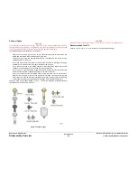
Standard Orientation of the Printer
When needed, printer orientation is called out in the procedure as an aid to locating parts.
Refer to
Figure 1
to identify the right, left, front, and back sides of the printer.
Figure 1 Printer Orientation
Preparation
CAUTION
Following reassembly, but before restoring power, be sure the components are all in their
home positions, otherwise damage to the printer will occur. Refer to the Adjustment proce-
dures at the end of this chapter for procedures on setting components to their home positions.
Before you begin any removal procedure:
1.
Switch off the printer power and disconnect the power cord from the wall outlet.
2.
Disconnect all computer interface cables from the printer.
3.
Wear an electrostatic discharge wrist strap to help prevent damage to the sensitive elec-
tronics of the printer circuit boards.
4.
Allow adequate time for the printer to cool.
NOTE: Names of parts that appear in the removal and replacement procedures may not
match the names that appear in the Parts List. For example, a part called the Registration
Chute Assembly in a removal procedure may appear on the Parts List as Assembly,
Chute REGI.
Notations in the Procedures
•
The notation “(REP X.X.X)” points to a prerequisite procedure in the current disassembly
procedure being performed.
•
The notation “PLX.X.X” indicates that this component is listed in the Parts List.
•
The notation “XX in.-lbs. is the torque specification for the subject fastener.
•
Bold arrows in an illustration show direction of movement when removing or replacing a
component.
•
The notation “(plastic T-20)” or “(metal, T-20)” refer to the type of screw being removed.
Plastic refers to a metal, self-tapping screw used to secure parts onto plastic. Metal refers
to metal, fine-threaded screws used to secure parts onto metal.
Содержание COLORQUBE 8570
Страница 1: ...ColorQube 8570 8870 Printer ColorQube 8570 8870 Service Manual Xerox Internal Use Only...
Страница 2: ......
Страница 152: ...October 2012 3 2 ColorQube 8570 8870 Service Manual Revised 3rd Revision Xerox Internal Use Only Image Quality...
Страница 196: ...October 2012 4 2 ColorQube 8570 8870 Service Manual Revised 3rd Revision Xerox Internal Use Only Repairs and Adjustments...
Страница 304: ...October 2012 5 2 ColorQube 8570 8870 Service Manual Revised 3rd Revision Xerox Internal Use Only Parts List...
Страница 316: ...October 2012 6 2 ColorQube 8570 8870 Service Manual Revised 3rd Revision Xerox Internal Use Only General Troubleshooting...
Страница 372: ...October 2012 7 2 ColorQube 8570 8870 Service Manual Revised 3rd Revision Xerox Internal Use Only Wiring Data...
Страница 392: ...October 2012 8 2 ColorQube 8570 8870 Service Manual Revised 3rd Revision Xerox Internal Use Only Theory of Operation...
Страница 423: ......


