


Manual 26247
2301D/2301D-EC Digital Control
Woodward
87
When the Baseload contact connected to terminal 38 is closed proportional load
sharing is terminated and the load is ramped either up or down to the baseload
reference setting.
Droop mode allows operation of a generator on an infinite bus or in parallel with
other engine generator units using hydromechanical governors. In droop, speed
changes as the load on the generator changes. An increase in load results in a
decrease in speed. The amount of speed change or droop is expressed in
percent (of rated speed) and is set by the load droop set point.
Droop Mode
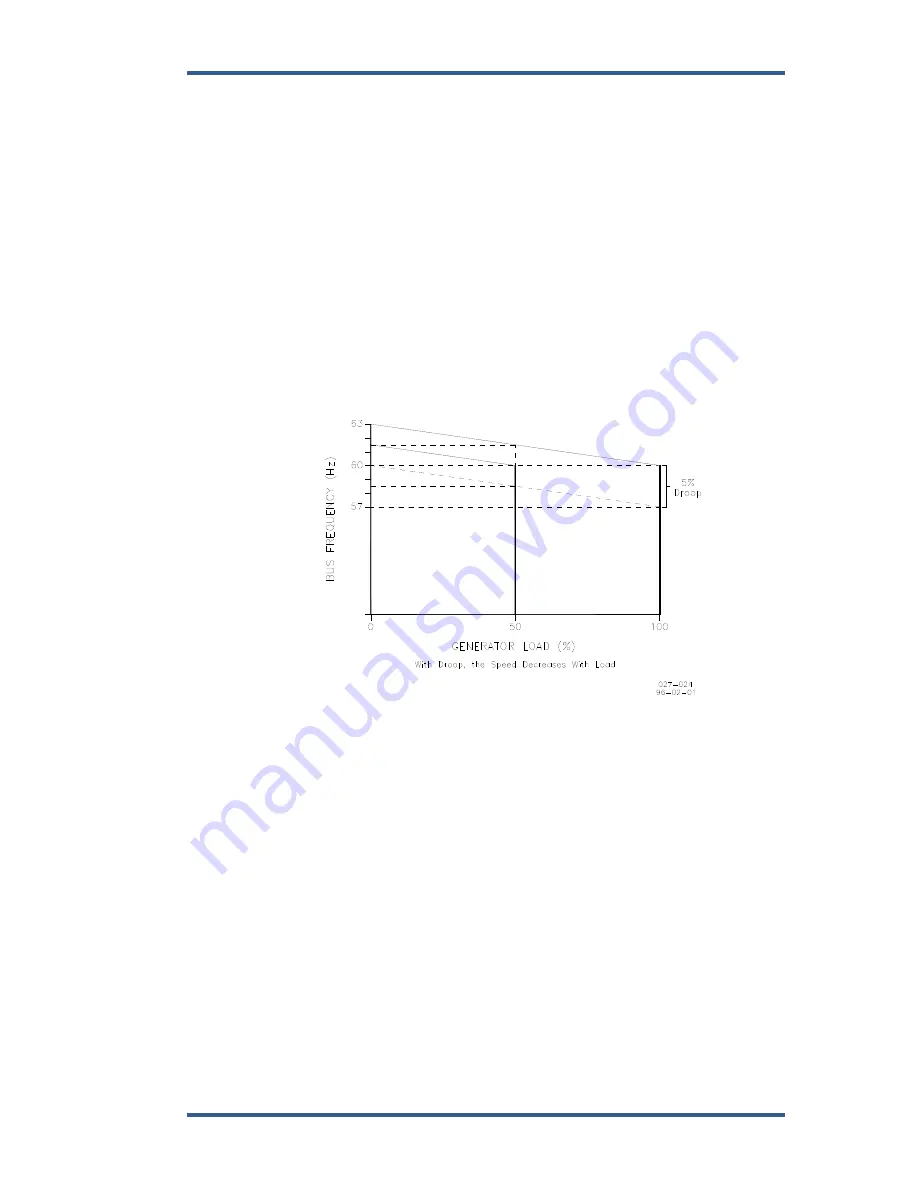
Droop is a decrease in speed or frequency, proportional to load. That is, as the
load increases, the speed or frequency decreases, as illustrated in Figure 6-5.
This reduction in speed is accomplished with negative feedback. The feedback
increases as the system is loaded.
Figure 6-5. Droop Mode
Droop is expressed as the percentage reduction in speed that occurs when the
generator is fully loaded. With a given droop setting, a generator set will always
produce the same power output at a particular speed or frequency. Droop is
sometimes called the percent speed regulation. If all generator sets in a droop
system have the same droop setting, they will each share load proportionally.
The amount of load will depend on their speed settings. If the system load
changes, the system frequency will also change. A change in speed setting will
then be required to offset the change in feedback and return the system to its
original speed or frequency. In order for each generator set in the system to
maintain the same proportion of the shared load, each generator will require the
same change in speed setting.
Содержание 2301D
Страница 12: ...2301D 2301D EC Digital Control Manual 26247 4 Woodward Figure 1 1a 2301D Outline Drawing Ordinary Locations ...
Страница 13: ...Manual 26247 2301D 2301D EC Digital Control Woodward 5 Figure 1 1b 2301D Outline Drawing Hazardous Locations ...
Страница 14: ...2301D 2301D EC Digital Control Manual 26247 6 Woodward Figure 1 2a 2301D Plant Wiring Diagram sheet 1 ...
Страница 16: ...2301D 2301D EC Digital Control Manual 26247 8 Woodward Figure 1 2c 2301D Plant Wiring Diagram notes ...
Страница 51: ...Manual 26247 2301D 2301D EC Digital Control Woodward 43 Figure 3 4 Typical Transient Response Curves ...
Страница 127: ...Manual 26247 2301D 2301D EC Digital Control Woodward 119 ...
Страница 129: ...Declarations ...