


2301D/2301D-EC Digital Control
Manual 26247
86
Woodward
Power System Management Concepts
This section provides a summary review of droop, isochronous,
droop/isochronous, isochronous load sharing, and base load operating concepts.
These concepts provide an understanding for power management.
Paralleling
There are two basic methods used for paralleling: droop, where speed decreases
with load increase, and isochronous, where speed remains constant with load
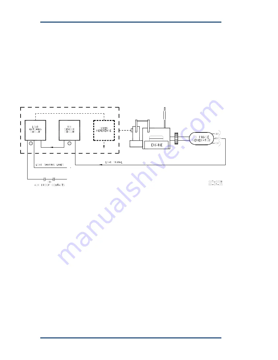
increase. The paralleling system shown in Figure 6-4 consists of a load matching
circuit (1),and kW sensor circuitry(2).
Figure 6-4. Paralleling System
An auxiliary contact on the generator breaker connected to terminal 34 is used to
select isochronous load control operation. A contact in series with the auxiliary
contact may be used to select either the droop or isochronous mode of operation.
When the input to the CB Aux contact is open, the control is in droop. When the
CB Aux contact is closed, the control is in isochronous load control.
With only one unit on line, the generator picks up the available load and remains
at isochronous speed. If other units are on line and the load command discrete
input is open, the load will immediately load to the Unload Trip Level setting.
When the Load contact connected to terminal 37 is closed the load matching
circuit corrects the fuel output to proportion load.
The Load sensor computes the load carried by each phase of the generator. The
current load on each phase is multiplied by the cosine of the phase difference
between the current and the voltage, and the three phases are added to
determine the total load.
The output of the load amplifier is adjusted by the load gain set point. By setting
the load gain voltage on each unit to the same level at full load, proportional load
sharing is achieved. Regardless of differences in generator set capacities in the
system, each generator set is loaded to the same percentage of its capacity. A
final adjustment of the individual load gain adjustment will compensate for minor
differences in the generator sets.
Содержание 2301D
Страница 12: ...2301D 2301D EC Digital Control Manual 26247 4 Woodward Figure 1 1a 2301D Outline Drawing Ordinary Locations ...
Страница 13: ...Manual 26247 2301D 2301D EC Digital Control Woodward 5 Figure 1 1b 2301D Outline Drawing Hazardous Locations ...
Страница 14: ...2301D 2301D EC Digital Control Manual 26247 6 Woodward Figure 1 2a 2301D Plant Wiring Diagram sheet 1 ...
Страница 16: ...2301D 2301D EC Digital Control Manual 26247 8 Woodward Figure 1 2c 2301D Plant Wiring Diagram notes ...
Страница 51: ...Manual 26247 2301D 2301D EC Digital Control Woodward 43 Figure 3 4 Typical Transient Response Curves ...
Страница 127: ...Manual 26247 2301D 2301D EC Digital Control Woodward 119 ...
Страница 129: ...Declarations ...