


Manual 26247
2301D/2301D-EC Digital Control
Woodward
69
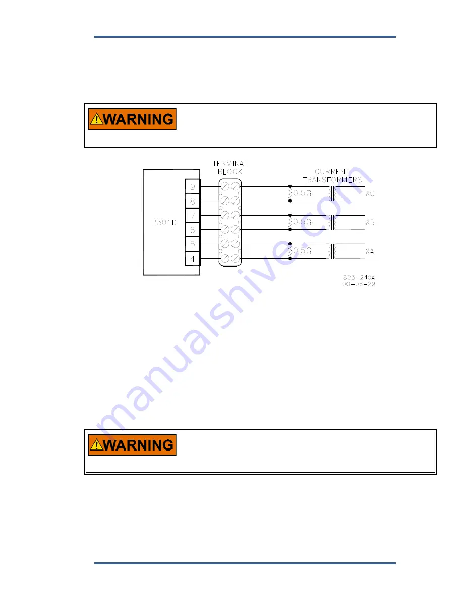
The Phase Correction Procedure requires that the prime mover be shut down
many times to disconnect the current transformers. For convenience, a
temporary method of connecting the current transformers shown in Figure 4-1 is
recommended. Connecting a 0.5
, 20 W burden resistor across each current
transformer allows the current transformers to be disconnected from the terminal
strip with the prime mover running, after removing all load.
HIGH VOLTAGE—The current transformers can develop dangerously
high voltages. Do not disconnect a current transformer while the
prime mover is running unless temporary 0.5
, 20 W resistors are
installed as shown in Figure 4-1, and all load is removed.
Figure 4-1. Temporary Wiring for Transformer Phase Correction
If the temporary burden resistors described above and shown in Figure 4-1 are
not used, the prime mover MUST be shut down in addition to removing the load
in the following procedure.
Monitor the load sensor output in this procedure by connecting an external
computer and entering the Watch Window sheet for
T**KW INPUT
CALIBRATION**
. Observe
03 Gen Output (read KW)
Load Sensor calibration
and monitoring. Since the kW calibration cannot be completed until the phasing
is correct, the value shown is for reference only. The Load Sensor of the 2301D
will only read a small negative value.
1. Shut down the prime mover.
HIGH VOLTAGE—The current transformers can develop dangerously
high voltages. Do not disconnect a current transformer while the
prime mover is running unless temporary 0.5
, 20 W resistors are
installed as shown in Figure 4-1, and all load is removed.
2. Label each CT wire with the phase and polarity that you think it should be.
Even though this identification may prove to be incorrect, this step is
necessary so that the individual wires can be identified during the description
of the procedure.
3. Disconnect the phase B CT wires from terminals 6 and 7. Connect these two
wires together using a small screw and nut, and tape the connection.
Содержание 2301D
Страница 12: ...2301D 2301D EC Digital Control Manual 26247 4 Woodward Figure 1 1a 2301D Outline Drawing Ordinary Locations ...
Страница 13: ...Manual 26247 2301D 2301D EC Digital Control Woodward 5 Figure 1 1b 2301D Outline Drawing Hazardous Locations ...
Страница 14: ...2301D 2301D EC Digital Control Manual 26247 6 Woodward Figure 1 2a 2301D Plant Wiring Diagram sheet 1 ...
Страница 16: ...2301D 2301D EC Digital Control Manual 26247 8 Woodward Figure 1 2c 2301D Plant Wiring Diagram notes ...
Страница 51: ...Manual 26247 2301D 2301D EC Digital Control Woodward 43 Figure 3 4 Typical Transient Response Curves ...
Страница 127: ...Manual 26247 2301D 2301D EC Digital Control Woodward 119 ...
Страница 129: ...Declarations ...