


Manual 26247
2301D/2301D-EC Digital Control
Woodward
27
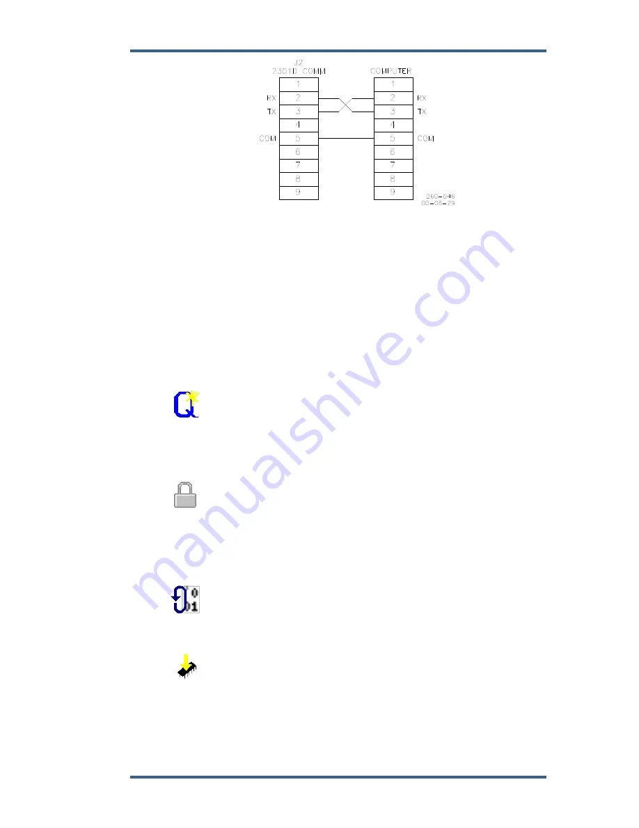
Figure 3-1. Null Modem Cable
Figure 3-1 shows the required connections in the null modem cable. These are
the minimum connections, some purchased null modem cables have more
interconnects, which are not used by the control.
The 2301D default baud rate is 38400, which needs to be entered in the Servlink
Network Options window. Servlink will be initialized correctly for all other port
parameters except BAUD rate.
Check the ‘pull-down’ menu CONTROL \ PROPERTIES to display the part
number and revision level of the software in the control. Refer to this number and
revision level in any correspondence with Woodward. The Watch Window
software has extensive help assistance through the Help Menu.
Watch Window version 1.05 and above allows for automatic generation of
inspector sheets. Click on the
Q
icon (Quick Inspector) on the tool bar. A Sheet
will automatically be created from each Service and Configure Header
programmed into the control. Multiple inspectors can be created this way to allow
for viewing more than one sheet at a time.
To enter the
I/O Lock
mode and enable a configure value to be entered,
click on the I/O Lock icon on the Tool Bar. Because the values set in Configure
are critical to engine operation, it is not safe to operate the prime mover while
these parameters are being configured. In the Configure mode the control
outputs will be set to their off state, and the microprocessor will stop executing
the application code. The control will have to be Reset to continue operation.
The
Reset
icon allows the microprocessor to store the configure
parameters, to return the outputs to their active state, and to resume executing
the application software.
When the tuning or setting of parameters is complete, the values must be
saved in the control’s non-volatile memory. Go to the Tool Bar and click the
PROM icon for
Save Values
. The values will be saved in non-volatile memory
and will be unaffected by loss of power to the control.
Содержание 2301D
Страница 12: ...2301D 2301D EC Digital Control Manual 26247 4 Woodward Figure 1 1a 2301D Outline Drawing Ordinary Locations ...
Страница 13: ...Manual 26247 2301D 2301D EC Digital Control Woodward 5 Figure 1 1b 2301D Outline Drawing Hazardous Locations ...
Страница 14: ...2301D 2301D EC Digital Control Manual 26247 6 Woodward Figure 1 2a 2301D Plant Wiring Diagram sheet 1 ...
Страница 16: ...2301D 2301D EC Digital Control Manual 26247 8 Woodward Figure 1 2c 2301D Plant Wiring Diagram notes ...
Страница 51: ...Manual 26247 2301D 2301D EC Digital Control Woodward 43 Figure 3 4 Typical Transient Response Curves ...
Страница 127: ...Manual 26247 2301D 2301D EC Digital Control Woodward 119 ...
Страница 129: ...Declarations ...