


Manual 26247
2301D/2301D-EC Digital Control
Woodward
11
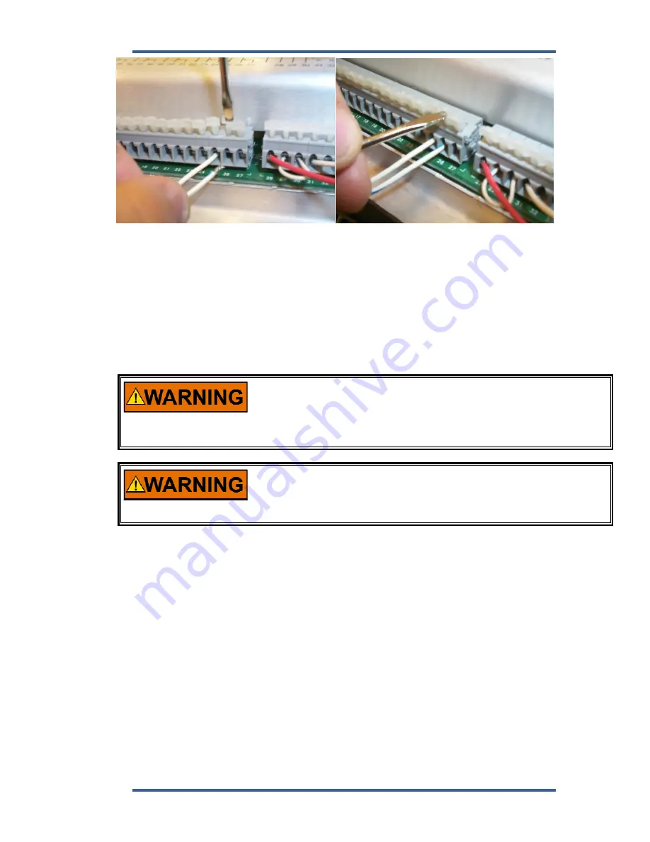
Figure 2-1. Installation of Wiring into Terminal
Setting Speed Range
The Microprocessor inside the 2301D calculates the speed range to be used by
entering the engine/generator synchronous speed and number of gear teeth.
This configured speed sets the hardware-to-software scaling. The rated speed
setting is set in service as the speed reference selected when the Rated switch is
closed.
The number of gear teeth is used by the control to convert pulses
from the speed sensing device to engine rpm. To prevent possible
serious injury from an overspeeding engine, make sure the control is
properly programmed to convert the gear-tooth count into engine
rpm. Improper conversion could cause engine overspeed.
The speed range is factory set for 900 Hz, 900 rpm (60 teeth). Refer to
Chapter 4 to change speed range and prevent possible overspeed.
Using the wrong speed range could cause an overspeed with
resulting damage to equipment or personal injury or death.
Potential Transformer Connections
Connect the potential transformer secondary leads to the following terminals:
Phase A to terminal 1
Phase B to terminal 2
Phase C to terminal 3
The potential transformer secondary line-to-line voltage must produce 90 to 120
Vac or 200 to 240 Vac. Refer to the plant wiring diagram, Figure 1-2.
Current Transformer Connections
The standard method of connecting the current transformers is shown in the
plant wiring diagram, Figure 1-2. An alternate method is the open delta
connection shown in the insert in the plant wiring diagram.
Содержание 2301D
Страница 12: ...2301D 2301D EC Digital Control Manual 26247 4 Woodward Figure 1 1a 2301D Outline Drawing Ordinary Locations ...
Страница 13: ...Manual 26247 2301D 2301D EC Digital Control Woodward 5 Figure 1 1b 2301D Outline Drawing Hazardous Locations ...
Страница 14: ...2301D 2301D EC Digital Control Manual 26247 6 Woodward Figure 1 2a 2301D Plant Wiring Diagram sheet 1 ...
Страница 16: ...2301D 2301D EC Digital Control Manual 26247 8 Woodward Figure 1 2c 2301D Plant Wiring Diagram notes ...
Страница 51: ...Manual 26247 2301D 2301D EC Digital Control Woodward 43 Figure 3 4 Typical Transient Response Curves ...
Страница 127: ...Manual 26247 2301D 2301D EC Digital Control Woodward 119 ...
Страница 129: ...Declarations ...