


Manual 26247
2301D/2301D-EC Digital Control
Woodward
41
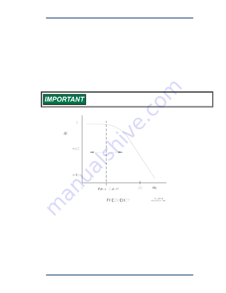
06 SPEED FILTER FREQ 1 (HZ)
dflt = 20.00 (4.00, 20.00)
Adjusts the cutoff frequency of a low-pass filter used on the engine speed
sensing input (see Figure 3-3). To use this feature set the cutoff frequency below
15.9 Hz. The filter is used to attenuate engine firing frequencies. To calculate the
desired filter cutoff point, use the following formulas:
camshaft frequency
= (engine rpm)/60
[for 2-cycle engines]
= (engine rpm)/120
[for 4-cycle engines]
firing frequency
= camshaft frequency x number of cylinders
Initially set the filter frequency to the firing frequency.
As the filter frequency is reduced, steady state stability improves but transient
performance may worsen. As the filter frequency is increased, steady state
stability worsens but transient performance may improve.
If the calculated firing frequency is greater that 15.9 Hz, then disable
the filter by setting the filter cutoff frequency at or above 15.9 Hz.
Figure 3-3. Speed Filter
07 BUMP ACT TRIGGER (T THEN F)
dflt = FALSE (FALSE, TRUE)
Allows you to test your dynamics settings by temporarily applying a decreased
fuel demand transient to stimulate a control response. Both the magnitude (Act
Bump Level) and duration (Act Bump Duration) of the transient may be set. The
actuator bump must be enabled in the ACTUATOR BUMP menu. To initiate an
actuator bump, toggle Bump Act to TRUE then back to FALSE while the engine
is operating in a normal steady state loaded or unloaded condition.
Figure 3-4 illustrates prime mover starts with the RAMP TIME set to minimum (no
ramp), step loadings at four different RESET settings, and stable, steady-state
running conditions. These are typical performance curves on a naturally
aspirated (non-turbocharged) diesel engine.
Содержание 2301D
Страница 12: ...2301D 2301D EC Digital Control Manual 26247 4 Woodward Figure 1 1a 2301D Outline Drawing Ordinary Locations ...
Страница 13: ...Manual 26247 2301D 2301D EC Digital Control Woodward 5 Figure 1 1b 2301D Outline Drawing Hazardous Locations ...
Страница 14: ...2301D 2301D EC Digital Control Manual 26247 6 Woodward Figure 1 2a 2301D Plant Wiring Diagram sheet 1 ...
Страница 16: ...2301D 2301D EC Digital Control Manual 26247 8 Woodward Figure 1 2c 2301D Plant Wiring Diagram notes ...
Страница 51: ...Manual 26247 2301D 2301D EC Digital Control Woodward 43 Figure 3 4 Typical Transient Response Curves ...
Страница 127: ...Manual 26247 2301D 2301D EC Digital Control Woodward 119 ...
Страница 129: ...Declarations ...