2
3
•
I
I
I
,
:J
,
I
I
- -
--
-
---
--
I
I
---
------
,
,
I
2
V
,
'J
V
Group
28
ignition s
y
s
t
ems
Fault
traci
n
g,
EZ·102K
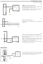
H6
power
stage
ground lead
M
easure
resistance between
co
nnector terminal 2
and
ground
.
R
esistance
should
be
0 ohm
.
If
readi
ng
is different
: Check lead
(s
ee wiring
diagram
)
.
Ground
term
i
na
l is
on
i
ntake manifold
.
H7
Check
s
creen
connections
Check
that
screen of
l
ead
to
t
ermina
l
5 is co
nnected to
terminal
3
.
H8
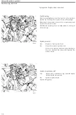
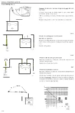
Check
signal
from control unit to power stage
Di
sconnec
t
leads
from ignit
i
on
coil
t
e
rminal
1
(
r
ed!
w
hite)
and
1
5 (b
l
uel.
Mea
sure
voltage between
t
erminal
5
or
6
in
p
ower
s
t
age
co
nn
ec
t
o
r
and ground
.
Operate
sta
rt
e
r
motor.
Voltmeter
should indica
te
approx. 2 V
.
No
reading
:
See
t
op of
page
146
.
Re
co
nne
c
t
coi
l l
eads.
Re
con
nect
power stage co
nn
ecto
r
.
'3
12V
V
Undo d
is
tr
ibu
t
or con
nector
.
Swi
t
c
h
on igni
ti
on.
Mea-
sure
voltage between pos
i
t
i
ve term
i
nal
(
red
l
ead
)
and
ground
.
R
ead
i
ng
should
be approx
.
12 V
.
139


