Gr
o
up
28
Ignition syst
ems
F
a
ult
Rex
-
I
12V
I
,
,
, ,
V
'
,
•
,
,
:
'
...
,,2
on
,
,
,
,
:
'
20
,
,
, ,
,
,"'813
...
---
....
"
,
220
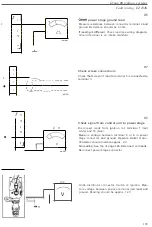
diode tester between
diagnostic
LED and
test lead
Connec
t
red
probe
on
diode tester t
o
pin under
LED
and black
probe t
o
t
es
t
lead
.
LED
is
ope
rating
correctly if
diode tester g
i
ves indica-
t
i
on
.
Repl
ace
diagnos
l
i
c
unit
if no indica
t
ion
is
observed.
N19
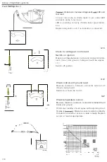
Check for
voltage
at control
unit
Sw
i
tch
on ignition
Mea
s
ure
vol
tag
e
between
con
trol
unit connector
termi-
nal 6
(blue)
and ground
.
Vol
tage
should
be
approx
.
12
V.
Switch off ignition.
N
20
Check
co
ntrol unit
ground
lead
Mea
s
ure res
i
stan
ce
between connec
tor t
erminal
20
(b
rown
)
and ground
.
Re
sis
t
ance should
be 0 ohm
.
N21
Check temperature
sensor
M
easure
resistan
c
e
between co
nne
c
tor t
e
rminal
2l
r
edl
b
l
ack) and ground
.
Ohmme
ter
reading
shou
ld
agree
with
adjoining chart
.
If value
is
Measure sensor
r
es
istan
ce
directly
1
0
determ
i
ne whether
sensor
or
lead
is
faulty
.
Repla
ce
sensor or
l
ead as appropriate
.
n
....
.
.
....
..
I I
'L
,
'
.
:
..
1
11
,_
·
•• ·u
•
•
•
•
•
••
..
•
•
..
..
••
•
..
.
..
.
' "
•
•
•


