Group
28
Ign
ition
systems
D
esign and function
System descriptions
..
4
60
EZ
-
102K
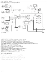
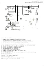
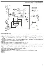
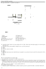
Control unit connections
1
.
Rece
ives
power from battery
(
1
)
l
h
rough
ignition switch (2).
2
.
Transm
i
ts
speed signal
to fuel
system control unit
(217)
4
.
Connected to
ground
by throttle
switch
(19
8) when throttle
closed
.
5. Transmits fault
signals
t
o
test terminal
(267)
when fault tracing with
t
est
diode.
6. Receives engine speed and
crankshaft position
signal from Hall generator in distributor (5)
.
8.
Re
ceives signa
l
from knock
sensor (218).
9.
Transm
its igni
tion
pulses to power stage (133).
1
0.
Re
ce
ives
12 V
supp
ly
on closure
of
thermostat
(2
24).
11
.
Grounds
con
lrol
unit
(260).
1
2
.
Grounds screen
of
lead from Hall
generator in
distributor
(5).
1
3
.
Supplies power
t
o
Hall generator
in
distributor (5).
14. Rec
eives load signal
from fuel
system control unit
(
217)
.
15
.
Grounds
screen of
knock
sensor
(
218)
lea
d
.
Power
stage
connections
1
.
Controls
current
in igni
t
ion coil (
4
)
primary
w
in
d
ing.
2
.
Grounded.
3
.
Grounds screen of
l
ead
connected
t
o
termina
l
5.
4
.
Receives
power from
battery
across
igni
tion
switch
(
2
).
5
.
Receives
ignition pulses
from
con
trol
unit
(260).
48


