Group
28
Ign
i
t
ion
systems
D
esign
and function
-
Components
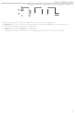
Output unit
D
.
The
digital
information supplied by
the
microprocessor
is
fed 10
the
output unit
(D)
for
conversion
in
to the
ignition
pu
lses
fed to th
e
power stage
.
(This may either
be
an
integral
part
of
t
he control
unit
or a separate uni
t
.)
Depend
ing
on
th
e
program selected at
t
he particular instant,
t
he
con
trol
unit de
t
ermines
the
p
oin
t
at which
t
he igni·
tion
pul
s
e must
be delivered to
t
he
power
stage.
The
la
tt
er con
t
rols
the
current
in the primary
winding
of
th
e
ignition
coi
l
in
re
sponse
t
o
the
signa
l
s
f
rom
th
e
output
unit.
Voltage
stabilizer
The
con
trol
unit
powered by
a
12
V
supply.
However
,
since
the
ba
he
ry voltage
too
high
for
the
internal
integ
rat
ed
circuits
,
a
vol
tag
e stabilizer
is
used
t
o
produ
ce
a stabilized
5 V
supply for
these
.
•
Engine
limitation:
A
ll control
units are programmed with
type
of speed limiting
function. On
Bend
ix systems,
the
unit normally commands the
stage to reduce the
Ignition coil
charging period. producing a weaker
spark
limils the eng
i
ne
output
.
On
EZ-K
systems,
Ihe
conlroi unit uses
Ihe
power slage
10
interrupl
l
he
spark
10
second plug.
The
speed
limiting funct
ion
normally inlervenes at aboul
r/min.
In
t
he case o
f
cars equipped
with
F
engines, the speed
function controlled by
Ihe
ignition syslem control unil
set
to
op-
era
t
e
81
a
higher
level than thaI
controlled by its fuel system coun
l
e
r
part.
T
his
prevents
unbu
rnl
fuel from reaching
Ihe
catal
yti
c
converte
r
,
with
the
a
nendant
risk
of overheating.
•
The
control
unit memory is
programmed with
a range of speed and load values. The unit improves the accuracy of control
by
in-
terpolating between Ihese
values, performing up to about
compu
tation
s
per minute to ensure
t
hat optimum
l
imi
ng
is
maintained
under
all conditions
.
As many as
4000
individual settings may be
computed
as
required
.
•
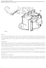
Built from
components such as
integrated
circuits
,
transistors, diodes and
electronic
componen
ts
like
the control unit
are relatively fragile
.
Since the electronics
in cars
are exposed to
a diversity
of operating conditions,
they
are subject to
particularly arduous demands
.
The equipment
mUSI
be
designed to withstand vibrations. moisture,
w
ide
temperature
fluctu
-
a
t
i
ons
,
variable voltages and
other
sources of outside interference
(e.g.
from rad
iosl
to
which the electrical system
is
unavoidably
exposed
.
•
In
th
e c
ase
of certain internal
fault
s,
the control unit regulates the
ignition in
accordance
w
i
t
h a
fixed.
pre-programmed
timing
c
urve
.
•
In Ih
e
absence
of
a load
signal,
Ihe
con
trol
unit modifies
the timing
on
basis
of
s
peed
signals
which
it re
ceives, and ope
r
-
ates
in accordance
with the
pre-programmed.
full
-load
timing
selling
when the
idling switch has opened.
•
the
k
nock sensor signal
is
lost. the con
l
rol unit
com
putes
the timing
setting on
Ihe
basis o
f
a
'fail-safe'
retardation of approx. 10"
.
•
The
control
unil
electronics must not
be
to excessively h
ig
h temperatures
.
For example, removal of the unit prior
to the
completion of
the
stoving process during
may result
its
destruction
.
Because of
its
sensitivity to temperature,
the
unit
is
normally
installed in
location
well protected from engine heal.
15

