Gro
u
p
28
I
gnition systems
D
esign and function
-
System
descriptions
,
n
•
,
,.
.
•
5
42
1
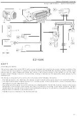
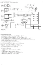
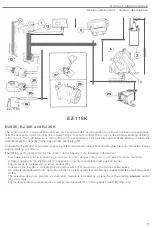
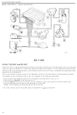
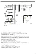
Banery
2
5 Distributor
6 Spark plug
Check engine
warning lamp
84
Coolanttemperalure sensor
86 Speedometer
t98
switch
218 Knock
sensor
260
cont
r
ol u
n
i
t
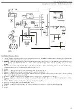
41
3 Speed/positio
n p
ick-up
420
Power
s
tag
eligni
t
ion coil
47
3
Regina control unit
482 Diagnostic unit
1
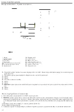
6. Transmits
ignition
pulses to power
s
tage
/ig
ni
t
ion coi
l
(420).
Power
stage
inte
r
rupts supp
l
y to
coil
whe
n
signal
goes low
(0 V).
17
.
Transmits
engine speed
signals to Reg
i
na
control
unit
(473)
terminal 1
.
18
.
Spare
.
19
.
Spare
.
20
.
Grounds
co
ntrol
unit
(
260)
.
21. Spare
.
22
.
Spare
.
23
.
engine speed and crankshaft pos
i
tion signals from
speedlposi
t
ion
pick-up
{
413
1
for
computation
of tim
-
ing.
24
.
Spare
.
25
.
Spare
.
Power
s
t
a
g
eli
gnit
i
on co
i
l conn
ecti
ons
a Grounds power
stageJignition coil
1
420
1 (sig
na
l
ground).
b
ig
nition
pulses
from
co
ntrol
unit (260)lerminaI16
.
Control
unit permits
charging of coil
through power
stage wh
ite sig
nal remains h
ig
h
(5 V)
.
Power
stage
opens terminal B
ground
connection when signal
goes
low
(0
VI
.
R
esultant
high tension
generated in ignition coil is distributed by
distributor
(5)
to appropriate spark plug
(6}.
A Receives
supply
from battery
(1) across
ig
nition switch
(2).
B
G
r
ounded
(supp
l
y ground).
C T
r
ansmits
signals cor
r
esponding to number of ig
ni
tion pu
l
ses
t
o speedome
t
e
r
(86) in combined inst
ru
me
nt
.
62

