Group
28
Ignition systems
Design
and function
- System descriptions
4
9
10
1
7
EZ
-
102K
EZ-102K
823FT
(760,1984 with 823FT)
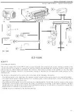
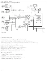
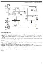
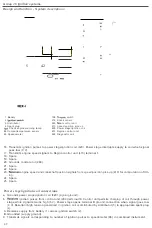
The
sensors supply
the
control
(
1)
with
a series of signals which descr
i
be the engine
running
conditions
.
The
control unit uses the signals to compute the optimum
timing
and
transmits the
necessary ignition pulses to
the
power stage
(
2), which
makes
and breaks
the
current in the primary winding of the
i
gnition coil (3). The
high
-
tension
current
thereby
induced in the secondary winding
is
de
l
ivered to the appropriate spark
plug
(4) by the
distributor
(5).
The timing
is computed by the control unit on the basis of the
following
i
nformation
:
-
The Hall
generator in the distributor (5) supplies a signal indicating
the
engine speed and crankshaft
position.
-
The engine load signal is supplied by the LH
-
2.1 in
j
ection
system control
unit
(9) which, in
turn
,
is supplied with
a
load
signal by the air
mass
meter (10)
,
-
Any
tendency of the engine to run hot is indicated by a
thermostat
(8).
(
The throttle must be closed and the engine
temperature
must
be
above
103
°
C before
the
control unit advances the
timing
.
Under
these
conditions,
the ther
-
mostat
will close, and
the
control unit will both advance
the
setting by
13
°
and switch in
the
electric radiator fan.
)
-
Engine knock
is indicated by the
knock
sensor
(
7
),
-
Throttle
closure is indicated by the throttle switch (6)
.
47

