Group 28 Igni
t
ion systems
Design and function
-
Components
Power stage and ignition coil
Function of power
stage
The
power
s
t
age
functions as an electronic
switch controlling
the
current in
the
ignition coil
on
command
from
the
control
unit
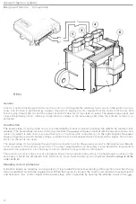
(31. (The
illustration shows the
components of
an
EZ
-K system.
In the Renix-F system, the power
stage
is
integral
with the
control unit,
although the principle
of operation is
the same
.
I
The function
of
the
power stage
analogous to that
of
the
points in
a mechanica
l
ignition system, in
that
it
alternate-
ly
opens
and
closes
the
coil
primary ground
connection.
Each time a
cylinder
fires,
the
power stage
interrupts
the
current in
the
primary
,
inducing a high-tension
vol
tage
in
t
he secondary.
Control
signal
Once the control unit has computed a
timing
se
tt
ing,
based
on
the signals from the various sensors,
th
e
value
is
con-
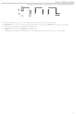
verted into a control
signal
for the power stage
.
When this
signal
goes high
(+5
VI, the power
stage
permi
t
s the igni-
tion coil
to
charge.
When the
signal again
falls
0 Vl,
the
power
stage interrupts
the
current in
the
ignition coil
pri
-
mary and
the
stored energy
is
released
in
the form
of
a high-tension pulse
i
n the
secondary.
Constant
charge
In
the
EZ
-K
and TZ-28H systems
,
the power
stage incorporates
a
which
continuously
monitors the primary
cu
rrent
used to
charge
the
igni
tion
coil
and
ensures
that the
charging current
remains
cons
tant
,
regardless of engine
speed or battery voltage. This feature
is
designed to ensure that
the
ignition
coil (2)
receives a constant
charge
at all
times
,
irrespective of
these
parameters. As a result, the
charge
in
the
coil
is
always a maximum and
the
ignition volt-
age remains
constan
t
ly
high.
Standing current protection
To
avoid overheating of
the
ignition
coil if
the
ignition
is
swi
tched
on with the engine
a
t
rest
,
the
control
unit in
-
corporates a circuit which operates the standing
current
protection function
via
the power
stage.
Since the
control
unit no longer receives signals from
t
he
Hall generator or speed pick-up
(whichever is
applicablel when the eng
i
ne
has been stopped
,
commands
the power
stage
to
interrupt
the
current in
the primary winding
of
the
coil.
Power
stage cooling
Since operation of the power stage generates heat, the unit
is
mounted
on
a heat sink attached
to the
body. Secure
contact between
the
unit and heat sink is essential to ensure
that
the working
temperature
is maintained
w
i
thin
ac-
ce
pt
able
l
imi
t
s.
The heat
is genera
t
ed
by the power circuit which
ac
t
s as
t
he 'wo
rk
ing'
sec
tion
of
t
he
power
s
t
age,
making the
'control' circuits vulnerable
t
o destruction. In systems in which the power stage is integral with
the
con
-
trol unit,
the
former
is
mounted on the
inside of
the
control unit frame to
ensure
adequate
cooling.
Ignition coil
The primary winding
of
the
ignition coil in an electronic ignition
system (
wh
i
ch generates
extremely
high voltages
up
to
a
co
ntinuou
s
30 kV
compared
with an average
of
15-18 kV
in
a
conventional coil) has
a relatively
low resist-
ance
.
Consequently
,
coils of
this type are fitted with a plug
(4)
which
opens
to
the pressure in the unit
in
the
event
of
over
heat
ing
and prevent deformation
.
NOTE
:
The plug
muat
be
f
i
tted
with a
cap
in the
case o
f
a
coil
ins
talled
vertically in
t
he
engine
compartment
.
17

