Group
28
Ignition
systems
Design and
fun
c
t
io
n
System
descriptions
4
E
Z
-
118
K
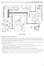
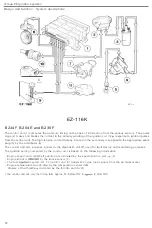
EZ
-118K
B200E
,
B230E and B230K
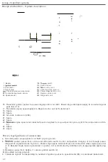
The
con
tr
ol
unit
(11
computes
the
op
t
i
mum t
imin
g on the bas
is
of
informa
t
ion
from
the
various sensors and
trans
-
mits the necessary
ignition
pu
ls
es 10
t
he
power
stage
/21.
wh
ic
h
con
trol
s
Ihe
curren
t
in
the primary wind
i
ng
of
the
ig-
nition
coil (3).
The
high
-
tens
ion current induced in
the secondary
w
inding
by
interruption of
the primary
is
fed to the
distributor
for delivery
to
the appr
opri
ate
spark
plug
Variants
for the B
230 K
e
ng
ine
also
sup
ply
signals
to a
solenoid valve
(
25)
controlling
the fuel
cut-off
function under
engine
brak
ing conditions.
The timing
selting compu
t
ed
by the
con
tr
ol
unit is based
on
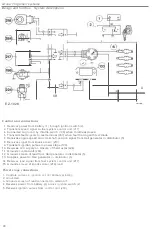
the following information
:
-
An engine load
signal
supplied by
a
vacuum line
(
12
)
between the
control unit
and the
intak
e
manifold.
-
A
Hall
generator
in
the distr
i
butor
(
4
)
supplies an eng
i
ne
speed/crankshaft
position signal.
-
Eng
ine
knock is indicated by a
kno
ck
sensor
(26).
-
Closure of the throttle
is i
ndicated by a throttle switch
(
19
)
mounted
on
the
thr
o
ttle
cable
pulley.
-
On
models
equipped with
AC
,
operation of
the
comp
res
so
r
(2
8)
is indicated
by
a
si
gnal from the
electromagnetic
clutch.
-
The
selection of a drive position
on
automatic models
is indic
ated
by a signal from
the
starting
swi
t
ch
(27)
via a relay
.
-
Engine temperature
is
measured by a
temp
erature
sensor
(
201
in the
c
ylinder head
(
B
230
only).
5'


