Group
28
I
gnit
i
on systems
Fault
tracing,
R
ex-'
;
:
"
T
-
23
,
,
,
,
,
,
'
,
1
17
N24
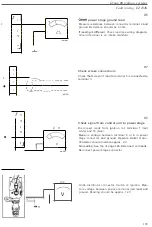
Check pulse generator
Measure
r
esistance
between
connector
terminals
10
(red)
and 23 (blue).
Resistan
ce
shou
ld
be approx. 240
±
25
ohm.
•
•
23
1
•
,
11
'
:
•
•
_-
_
10
,
,
,
,
,
, ,
,
,
,
:
1
44 8
11
,
'
Check
that
screen is connected
to terminal
11
.
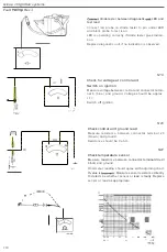
Check knock
sensor
leads
Undo knock sensor connector and
bridge terminals
1
and 2
.
Measure
r
esistance
between terminal 12
(b
la
ck)
and
13
(green)
in
contro
l
unit
connector.
Resistance
should
be
o ohm.
If
r
esistance
is too
high
one
or
both leads
is
faulty
(o
pen-circuited). Remove
jumper and
measure
each
lead
separately
with
ohmmeter.
Replace damaged
lead(s).
If leads are
intact.
rep
lace
knock
se
n
sor.
T
ightening
torque
20
±
5
Nm (15
±
3.5
ft Ib)
.
Reconnect knock
sensor connector.
N25
1
2
144
818
3
2
1
44
819
1
1
222

