:
:
I
_ _
-
1
44
Group
28
Ig
n
i
t
io
n
s
y
s
t
ems
Fault tr
a
ci
n
g,
R
ex
-
J
N2
2
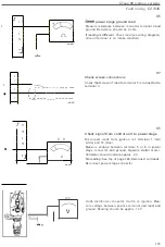
Check throttle switch
Measure resis
t
ance be
t
ween co
ntr
o
l
u
nit
co
n
nec
t
o
r
t
e
rmi
nal 7 (oran
g
e) a
n
d groun
d
.
R
esistance s
h
ou
l
d be a ohm.
D
ep
r
ess accele
r
a
t
or un
t
il th
r
o
ttl
e sw
it
c
h
opens s
light
ly.
R
es
i
sta
n
ce should
i
ncrease to infinity.
In c
a
se of fault
: Measure
t
h
r
o
ttl
e swi
t
c
h r
es
i
s
t
a
n
ce
rect
l
y
t
o es
t
a
bli
sh whe
th
e
r f
au
lt
is
wiring or sw
i
tch i
t
sel
f
.
necessary:
Check throttle switch setting
Open thro
ttl
e sli
g
h
tl
y and listen
t
o s
w
i
t
c
h
. C
li
c
k
s
h
ou
ld
be heard
(
as
i
dling co
n
tacts ope
n
)
imm
edi
at
e
l
y
t
h
r
o
ttl
e
opens.
Adjustment
Loosen mou
nt
i
ng screws (3 mm
All
e
n
sc
r
ews).
Turn s
w
i
t
ch slightly clock
w
ise
.
Turn sw
i
tch back counte
r
clockw
i
se un
t
i
l
cl
i
ck is hea
rd
from con
t
acts
.
T
i
ghte
n
screws.
Check adjustment.
,
:
I
I
IL
I
:
:
I
N
2
3
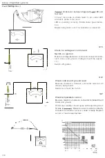
Check load signal from fuel system control unit
R
emove panel unde
r ri
gh
t
-
h
a
n
d s
i
de o
f
i
n
stru
m
e
nt
panel and panel at right
-
han
d
side of b
u
l
k
hea
d
.
R
e
-
move glove co
m
partmen
t
.
Undo fuel system co
nt
ro
l
unit connector.
M
easure resis
t
an
c
e between ign
it
ion sys
t
em co
n
nec-
to
r t
ermina
l
8
(
yellow) and
f
uel sys
t
e
m
co
nn
ec
t
o
r t
e
r
-
minal 25 (yellow
)
.
Ins
tr
ument should
r
ea
d
0 o
h
m,
o
th
e
rw
ise le
a
d is open
-
circuited
.
Chec
k
connecto
r
s as
per wiring diagram
.
If faul
t
pers
i
s
t
s al
t
houg
h
l
ead is
i
n
t
act, in
t
e
rn
a
l f
a
u
lt is
presen
t
in one of co
n
t
r
ol units
.
Replace pane
l
s and glove compa
rtm
ent
.
221


