Group
28
Ignit;on systems
Design
and
function
-
Overview
Review of electronic ignition systems - I
A
B
C
D
E
F
G
H
J
TZ-
28"
IlENIX
F
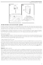
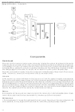
The above figure shows
the
major
componen
t
s
of each of the
systems
descr
i
bed below
.
Summary
Control system
The control unit
(
A
)
house
s
the
electronic circuits and
t
he
various program functions
ne
e
ded to
compute
the
timing
.
The power
stage (
B
l
cont
r
ols
the pr
i
mary
current in
t
he
ignition
coil
in response to
con
t
rol
signals
f
r
om the
con
t
rol
unit. The power
stage
may
either
be
an integral part of
the
control unit or a
sepa
rate
unit assembled
with
it.
The
func-
t
ion
of
the distr
i
butor
(e)
is
to
deliver
t
he
high-tension pulse
i
ndu
ce
d in
the
secondary
winding of
the
ignition coil to
the
correct spark plug
.
The
distr
i
butor may be dr
i
ven e
i
ther by
bevel
ge
aring
whi
c
h case
i
t
is ins
talled
vertically) or
directly from the
camshaft
(
hor
i
zontally
i
nstalled
units)
.
In
systems
which the
rotor
arm
the only moving part
(such
as types which employ inductive
speed
p
ic
k
-
ups
)
the lim
i
ng
ca
nnot be varied by alter
i
ng
the
pos
i
t
io
n of
the
distributor
.
Sensors
The
rema
ining
components in
the tab
le
(D-
E
)
c
omprise part of
the
senso
r
system.
T
ogethe
r
with
the
con
tro
l
un
it,
these
supply
i
nformat
io
n
on prevailing engine
running
c
onditions
.
Bas
i
c
parameters
The
con
trol
unit
is
supplied with information on eng
i
ne
spee
d
and
c
rankshaft position
(
D)
either by
a Ha
ll
generator
a
c
tivated
by a
trigger
rotor (with
four
vanes)
moun
t
ed on
the rotor
s
haft
or by an inductive
pick
-
up mounted
c
lose to
the flywheel
(on
manuals
)
or
ca
rrier
pIa
I
e
(automatics)
.
th
is
case,
the periphery
of the
flywheel
/c
arrier
plate
is
pro
-
vided with
a se
r
ies
of holes whose passage
detec
ted
by the
p
ick-up
and ind
ic
ated in the
form
of electrical signals
.
The
eng
i
ne load
(E)
measured either by means
of
a
vacuum
l
i
ne anached
t
o
th
e
i
ntake manifold
or,
if
the
eng
i
ne
is
equipped w
i
th an LH
-J
etron
ic
fuel
i
n
jec
t
io
n
system
(i.
e
.
most
engine
s
equ
i
pped with EZ
-
K
i
gnit
i
on systems
).
by an
a
i
r mass meter
(see
next
ill
ustration
).
Th
e
var
ious
signals
-
engine
speed
,
crankshaft posi
tion
and enQine load -
com
pr
ise
information which is used
by
ignit
i
on
systems
o
f
types to
compu
te the tim
i
ng
.
4


