Group
28
Ignition systems
Design
and
function - System descriptions
__
•
•
,
198
84
86
•
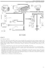
REX-I
Control un
it
conn
ecti
on
s
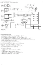
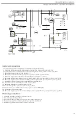
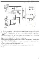
1
.
Transmits
signals to diagnosti
c
un
i
t
(
482
)
when fault trac
i
ng
.
Signals are
transm
i
ned
by
diagnosti
c
un
i
t when ap-
propriate diagnost
ic
funct
i
ons are sel
ec
ted
.
2
.
engine
temperature
signal from
temperature
sensor
(
84
)
for tim
i
ng compensation
.
i
f required
.
Contro
l
unit supplies
one of
NTC resistors
i
n
s
ensor
with
constant voltage
and
measures
resulting
voltage level
i
n-
ternally
.
3
.
Grounds
connection
when
certain types of
fault
are
present
in system
.
Ground
i
ng
closes
cir
c
uit
to
combined
strument,
illuminating 'Check
engine' warning lamp
(1217)
.
4
.
Spare.
5.
R
eceives
supply from battery
(1)
for
self
-
diagnostic program memory.
6.
R
eceives supply from battery
(1)
across
ignition switch
(
2)
terminal 15
.
7
.
R
eceives signal from throttle
switch
(
198) when throttle
i
s
fully
closed
.
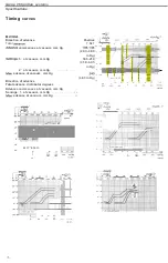
Control
unit
respond
by selecting
timing
curve
which is speed
-
dependent only
.
8
.
Receives engine
load s
i
gnal
from Regina
control un
i
t
(
473
)
f
o
r
c
omputat
i
on
o
f timing
.
10
.
eng
i
ne
speed and crankshaft pos
i
tion
s
i
gna
l
s
from
s
pee
d/
position p
i
ck
-
up
(
413
)
for computat
i
on of
tim
-
ing
.
11
.
Connection
for
screen
o
f lead from speed/p
o
s
i
t
i
on pick
-
up
(
413
).
12
.
Grounds screen of lead from
knock
sensor
(
218
).
13
.
signal
from kn
oc
k sensor
(
218
)
for retardation of t
i
m
i
ng in cyl
i
nder affected by
knock
.
14
.
Spare
.
15
.
Spare
.
6'


