Group
28
Ignition
sys
t
ems
Des
ign
and
fun
c
t
ion
E
ngine load in
f
ormation
1
4
F
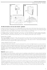
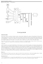
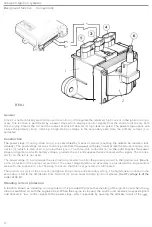
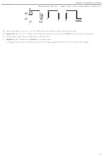
uel injection system control unit (LH-2.1. LH-2.2. LH-2.4)
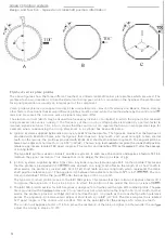
The fuel
sys
t
em con
t
rol
unit
(1j supplies
the
ignition system control uni
t
(2)
with
info
rmat
ion on
engine load.
Th
is
based
on signals
from
an air mass meter (3),
th
e quan
t
ity
o
f
induc
t
ion
air
being
used
as a
measure
of
th
e
l
oad.
Signal
The air
mass mete
r
con
t
inuously measures the
quant
ity
of air
drawn
in
t
o
the engine
and
delivers a variable
signa
l to
th
e
injection
system control uni
t
, i
n which the
signal
is
conve
rt
ed in
t
o
digital
f
o
rm
and
used
t
o compu
te
th
e
quantity
of
fuel to be
injec
t
ed. The signal
also
relayed
to
the
ignition sys
t
em cont
rol
uni
t
.
The
digital
signal
co
nsists
o
f
a
series o
f
current
pulses
(
4
) of a
durati
on (5)
proportional to
the
load.
Advantages
Th
is
type
of
load
info
r
ma
t
ion is used in
E2-K
systems
with LH-Jetronic fuel
injec
ti
on and
Rex-I systems
w
i
th
th
e
Regi
-
na
injec
ti
on
system,
and is
more accurate than that
supplied
by a vacuum
fr
om
the
in
t
a
ke manif
o
ld
.
In addition,
the
air mass
meter responds
more quickly and is
no
t
subject
to measurement
e
rr
o
r
s caused
by
variations
in air den
-
sity.
(In
o
ther
words,
i
t
is independent of air
temperature
and heigh
t
above
sea
leveL)
•
Should the fuel
s
ystem
control unit fail. for any reason. to supply
th
e
igni
t
ion
system control unit
with
a load signal,
the latter
w
ill
compu
t
e the
timing
on the basis that max.
load condi
ti
ons
prevail when the throttle has opene
d
.
26


