G
r
oup
28
I
g
n
i
t
ion sys
t
e
m
s
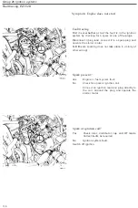
Fault tracing
,
R
ex-
I
Switch on ign
i
t
i
on
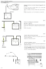
Connect test lead
to
socket 6
.
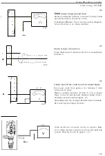
Measure
voltage between control
unit
connector
termi-
nail (yellow
/
red
)
and ground
.
Instrument should read
approx
.
12
V.
Depress pushbutton
.
Voltmeter should
now
read
0
V.
N15
Measure
at d
i
agnostic
unit
connector if voltage
is not present at control unit or
instrument
reads
1
2
V
with
pushbutton
depressed
.
N
I
B
Checking diagnostic unit
I
V
NIl
At d
i
agnostic unit
Me
.
sur
e
voltage betw
ee
n connector blue
a
nd
ground
Vol
t
mete
r
should
read
approx
.
1
2
V
.
and
ground
Ohmmeter should
read
0
ohm
.
ign
iti
on
NI
B
Measure resistance between diagno
s
tic unit test
lead and pin (No
.
8) under function selector
Ohmme
t
er s
h
ou
ld r
ead infi
n
ity
Press function
selector
button.
Ohmmeter should
now read 0
V.
219

