background image

Group

28

Ignition

systems

De

sign and function

General

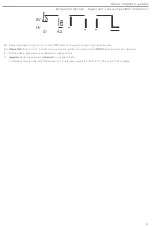
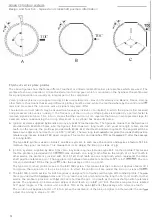
A

B

c

late ignition

C.

Late ign

it

ion

reduces

engine power since

the

pis

t

on is

t

ravelling downwards

from

ToC

when the

pr

essure

r

ise oc-

curs.

As

a

result

,

the

engine does not u

t

i

lize

t

he full

energy

content of the

fuel

.

Although

the

concentra

tions

of

unde

-

s

ira

ble constituents such as

HC,

CO,

NO

and

are lower under

these

conditions,

the

engi

n

e

require

s

more fuel t

o

deliver the

same

producing a greater

tota

l

volume of exhaust

gases.

Effects on

cylinder and exhaust

gas temperatures

Advancing the

ignition (i.e. generating

the

spark

to

ign

ite the fuel

/air

mixture

when

the pis

ton

is further from

ToC

)

produ

ces

a

h

igher combustion

temperature

and a

low

er

exhaust gas

temperature than when the

tim

ing

is

r

e

t

a

rd

ed.

Thi

s is due

to the

fact

that

the compression produced

by

upward movement of

the

pis

t

on

reinforces

the

pressure

w

ave

developed

by

t

he

flame

front, causing

the

cylinder pressure and

temperature to increase. The

lower

ex

hau

st

gas temperature

is explained

by the

somewhat longer

in

terval between

the completion of

combustion

an

d th

e open-

i

ng

of

the

exhaust valve.

R

e

tard

ing

the

igni

t

ion

(gene

rating

t

he spark when

the piston is

to

TD

C)

produces a

l

o

wer

comb

u

s

ti

o

n t

em

per

-

a

ture

,

bu

t

a

higher exhaus

t

gas

temperature than when the timing

is advanced. Under

t

hese condi

t

io

ns

, a h

i

g

her

pro-

portion of

t

he energy is released

during the

expansion stro

k

e (when

the piston is

moving

r

educin

g the

maximum temperature

somewhat. The higher exhaus

t

gas

t

emperature is explained by

the

s

h

o

rt

e

r

in

t

erval

between

the

comple

ti

o

n

of combustion and

t

he opening of

the

exhaus

t

valve.

-NOTE

;

It

is

important

that the

foll

o

wing terms be

c

learly

u

nderstood

in

o

rder

to avoid

con

fusion

:

a)

Advan

cing

the

ignition timing means

t

hat

the

igni

tion

pulse

is

delivered

when

the piston is at a point funher from

TOC.

b) Retarding

the

ignition

means that the

ignition

pulse is delivered

when

the piston

is

at a

point

closer to

TOC

.

Under normal

conditions,

the aim

to develop

'peak'

pressure in the cylinder about 10

"

after TOC. Under idling conditions,

the

timing

is advanced

(

t

o

approx. 10-15

"

before TOC) to ensure smooth

runn

ing

.

The

foregoing

discussion of how the emissions are affected by

th

e igni

tion

timing

is

somewhat simplified, since there are

natural·

Iy many other

factors wh

ich influence

th

e

composition of

the

e

xhaust

gases.

10

Содержание 819 E

Страница 1: ...700 1982 Section 2 28 Ignition systems TP 31397 1 July 1989 ...

Страница 2: ...34F 1988 B 230 F 1985 Volvos are sold in versions adapted for different markets These adaptations depend on many factors including le gal taxation and market requirements This manual may therefore show illustrations and text which do not apply to cars in your country Volvo owners planning to export their carls to another country should investigate the applicable safety and ex haust emission requir...

Страница 3: ...t power stage and ignition coil configurations 16 Power stage and ignition coil 17 Distributor 19 Speed and crankshaft position information Hall generator 20 Speed position pick up and flywheel configuration 22 Load information Induction manifold vacuum 25 Fuel injection system control unit 26 Compensation functions Theory of knock 28 Knock sensor 30 Knock control 32 Knock controlled fuel enrichme...

Страница 4: ... _ 135 EZ 115K 151 EZ 117 118K _ 169 EZ 116K 187 Aex I 21 5 See Service Manual Fault tracing repair and maintenance Section 2 23 B 23 B 200 B 230 ET Engines 740 760 Turbo for details of Motronic systems Order No TP 30949 1 Index page 227 Order No TP 31397 1 Supersedes TPI31059 1 USA We reserve the right to make changes without prior notification 2 e VOlVO NORTH AMERICA CORPORATION ...

Страница 5: ...lled by an electronic ignition system control unit include fuel cut off under engine braking deceleration conditions and ignition retardation in individual cylinders to eliminate knock Volvo markets a wide range of models with a series of engine options This combined with rapid developments in the field of electronics means that a wide variety of electronic ignition systems of different types and ...

Страница 6: ... inductive speed pick ups the liming cannot be varied by altering the position of the distributor Sensors The remaining components in the table D E comprise part of the sensor system Together with the control unit these supply information on prevailing engine running conditions Basic parameters The control unit is supplied with information on engine speed and crankshaft position D either by a Hall...

Страница 7: ...ll generator to supply the signals used by the control unit to control the primary current in the ignition coil A vacuum advance unit on the distributor varies the timing with engine load Although the system was used on some 700 series models produced in 1984 it was almost completely superseded by other systems in 1985 as the new family of engines entered production Un like other systems discussed...

Страница 8: ...amily of ideal timing curves for the particular en gine Each system also includes a sensor which detects engine knock and retards the ignition in response to a mem ory program which is individual to each cylinder This means that the timing in each cylinder may vary at any given instant As column E indicates systems in this group are normally supplied w ith engine load information by an air mass me...

Страница 9: ...ition pick up mounted at the flywheel Depending on the temperature sensor signal the control unit can apply timing compensation by retarding the ignition when the engine is cold to achieve faster heating of the coolant and by advancing it when the engine tends to run too hot The system appeared in 1987 with the introduction of the 8280 engine to replace the B 28 and is therefore used only on the 7...

Страница 10: ...28 A B 28 E B 28 F B 19 E B 23 E B 230 A B 23 ET 8200 ET B 230 ET B 200 K B 230 F B 23 FT 8230 F B 230 FT B 200 E B 230 E B 230 K B 230 K B 280 E B 280 F B 234 F B 230 F B 204 E YEAR 82 85 82 86 82 86 84 B4 8 S6 B4 85 85 85 89 84 USA 8 S8 85 85 85 85 86 87 87 87 88 89 89 N B Due to differences in model specifications from country to country the number of control unit variants used for the various ...

Страница 11: ... ratio and temper ature Furthermore the tim ing may be adjusted for optimum comfort maximum torQue or maximum power as ap propriate In the rest of this discussion the term optimum timing shall be taken to mean a setting which takes account of all the factors influenced by the ignition In other words it is a compromise between the demands of high power low fuel consumption and the cleanest possible...

Страница 12: ...on and the open ing of the exhaust valve Retarding the ignit ion generating t he spark when the piston is closer to TDC produces a lower combustion temper ature but a higher exhaust gas temperature than when the timing is advanced Under t hese condit ions a higher pro portion of t he energy is released during the expansion stroke when the piston is moving downwards reducing the maximum temperature...

Страница 13: ... downward movement of the pistons is faster under these conditions As a result the time available for combus tion of the fuel air mixture is less and the timing must be advanced to ensure that the mixture is burned as complete ly as possible Load information B Except in turbocharged engines the engine load varies with the vacuum in the intake manifold At low loads the throttle is only partially op...

Страница 14: ...for different engine types If the operating temperature is too low i e below about 400Q C the plug w ill rapidly become coated with combustion residues This type of fouling weakens the spark and causes the en gine to miss On the other hand if the operating temperature is too high over approx 1000 C the fuellair mixture may be ignited by the incandescent plug surfaces initiating uncontrolled combus...

Страница 15: ...e the vacuum advance unit retards it as the engine load increases in response to the vacuum signal from the intake manifold The two devices operate independently w ithin a tolerance band of approx 2 4 Overall this means that the system controls the timing within a tolerance range of approx 4 8 since the setting is the sum of the angles in dicated by the two curves Furthermore the variation which r...

Страница 16: ...gnals into digital numerical form Some of the sensors supply analogue signals such as the temperature dependent change in resistance typical of a temperature sensor while the signal transmitted by others depends on whether or not a voltage is present as in the case of a throttle switch The sensors may also transmit signals in the form of voltage pulses like an inductive pick up or a variable frequ...

Страница 17: ...anendant risk of overheating The control unit memory is programmed with a range of speed and load values The unit improves the accuracy of control by in terpolating between Ihese values performing up to about 1 סס oo computations per minute to ensure that optimum liming is maintained under all conditions As many as 4000 individual settings may be computed as required Built from components such as ...

Страница 18: ...it to the appropriate spark plug generating a spark across the eleClrodes and igniting the fuel air mixture A The control unit power stage and ignition coil may all be separate components This applies to EZ K systems B The control unit and power stage may be combined in a single unit with a separate ignition coil This applies to TZ 28H C The power stage and ignition coil may be combined with the c...

Страница 19: ...arge at all times irrespective of these parameters As a result the charge in the coil is always a maximum and the ignition volt age remains constantly high Standing current protection To avoid overheating of the ignition coil if the ignition is switched on with the engine at rest the control unit in corporates a circuit which operates the standing current protection function via the power stage Si...

Страница 20: ...e power stage and ignit ion coil wilh battery voltage grounds the coil and supplies the rev counter with a signal The connec tor 5 on the left is not used The power stage 1 incorporates the electrical circuits which control the primary current in the ignition coil Mount ed on a bracket in the engine compartment the power stagelignition coil assembly is provided with a large contact area with the s...

Страница 21: ...bevel gearing B Horizontal distributors are driven directly from the camshaft minimizing the play in the transmission mechan ism This in turn affords more accurate control of the timing in systems in which speed information is supplied by a Hall generator 700 series models from 1985 on with the exception of the 740 with the B230A engine are fitted with camshaft driven units In the case of distribu...

Страница 22: ...fier A magnet 4 with a three pole connector 5 is located on the opposite side of the rotor to the Hall IC element The connector terminals are connected respectively to a 12 V supply a 5 V reference signal from the control unit 01 and ground Signal A In this position the magnetic field is blocked by the trigger rotor vane and the Hall effect is absent No voltage is induced in the Halt IC element an...

Страница 23: ... compule timing of ne l ignition pulse A2 Signal faits from 5 to 0 V Conlrol unit commences ignition counldown and delivers ignition pulse as computed 8 Positive flank Hall element unaffected by magnetic field C Negative flank Hall element Influenced by magnetic field A Hall generalor is used on TZ 28H with a 12 V reference signal EZ l02K EZ 117K and EZ 118K systems 21 ...

Страница 24: ... is passing the tip Operation An alternating voltage is induced in the pick up coil when one of the projections or teeth on the flywheel passes the tip This variable signal is transmitted by a lead to the control unit In effect therefore the pick up supplies the control unit with a unique alternating voltage an electrical picture of the flywheel from which the unit can determine both the engine sp...

Страница 25: ...e must be taken to avoid striking the pick up w ith tools or dismantled compo nents The accuracy and reliability of the signal is dependent on maintaining the gap I t 10 5 mmf between the tip and the toothed profile for which the device is designed In addition the pick up must be mounted at right angles to the profite The greatest care must be taken when replacing the flywheel carrier plate if the...

Страница 26: ...eference points are located 180 apart angle a The control unit identifies TDC as th e point 90 after the passage of a long tooth The type 44 2 profile is used on Aenix F and Rex I systems In each case the control unit applies a factor of 8 18 to improve the signal resolution This means th at it can adjust the timing in steps of 1 00 8 Ignition systems supplied by Bosch for Volvo 4 cylinder engines...

Страница 27: ...ming Electrical vacuum converter B The vacuum line on the Renix F system is connected to a vacuum con erter integral with the control unit Al though each vacuum converter is designed specifically for a particular system the principle of operation is the same in all cases The vacuum is applied to one side of a spring loaded diaphragm 4 the other side of which car ries an iron core 5 mo ing inside a...

Страница 28: ...he signal is also relayed to the ignition system control unit The digital signal consists of a series of current pulses 4 of a duration 5 proportional to the load Advantages This type of load informat ion is used in E2 K systems with LH Jetronic fuel injection and Rex I systems w ith the Regi na injecti on system and is more accurate than that supplied by a vacuum line from the intake manifo ld In...

Страница 29: ...ls The electronic pressure sensor 3 and air temperature sensor 4 supply voltage signals to the Regina control unit Ill Taken together these signals provide a measure of engine load and are processed by the Regina control unit to compute the quantity of fuel to be injected Once the load signals have been converted into digital form i e into square wave pulses they are transmitted to the Rex I contr...

Страница 30: ...e spark compresses and heats the unignited m ixture to the point at which detonation is unavoidable A relatively high engine load is required to produce this type of knock Glow ignition knock B In the type of knock which occurs before the plug has delivered a spark detonation of the mixture may be due to incandescent carbon particles or gasket edges fou led spark plugs or other areas of the combus...

Страница 31: ...tem Excessively high combustion temperature Carbon deposits in Ihe combustion chamber WIll reduct the rate of heat dissipation resulting in high temperature land creating the risk of glow IgnitIon DefiCient cooling due for example to a faulty water pump radiator or thermostat or to rustnime deposits m the cooling passages Will have the time effect Incorrect or worn spark plugs The fisk of detonati...

Страница 32: ... sensor which responds by generating an output voltage Signal The signal delivered by the piezoelectric crystal consists of a continuous variable voltage of a frequency correspond ing to the engine vibrations The signal is fed to the control unit which computes a mean or reference value Sensing of signals The control unit is programmed specifically to detect signals of the frequency generated by k...

Страница 33: ...lb w ithout any adverse effect on the performance of Ihe device Although production of type 181 was discon tinued in 1986 it is fully interchangeable wilh type ICI Particular care muSI be taken when fining the older type 01 sensor a torque wrench must be used to lighten Ihe device in position Since the ignition may be retarded in each individual cylinder in the evenl of knock the tIming In each ma...

Страница 34: ...ntrol unit continuously computes the optimum timing on the basis of the running conditions On detecting knock the unit retards the ignition by a step of a few degrees 2_3 depending on the system in the cylinder affected If the phenomenon persists the setting is retarded by a further step and so on until the condition has been correct ed The maximum retardation in relation to the basic timing is ap...

Страница 35: ...8 0 37 Specified number of engine revolutions depending on speed Re advance step Re advance interval revolutions depending on speed EZ 118K lvalues for B230K 1985 86 8230E and B200E respectivelyl Max knock controlled retardation 15 16 9 8 12 6 Knock retardation step 2 8 2 8 8 7 depending on speed 2 8 2 8 0 35 in all cases Specified number of engine EZ 115K EZ 116K Rex I Max knock controlled retard...

Страница 36: ...n the engine is running the control unit computes the optimum ignition timing on the basis of speed and load signals The occurrence of knock in a cylinder is detected by the control unit which retards the ignition by a step of 3 in the cylinder in question If the phenomenon persists the control unit retards the ignition by a further step of 3 In 6 and so on until knock is eliminated Ae advance at ...

Страница 37: ...e mean value of the timing angle As already described advancing the timing point improves the effi ciency of fuel utilization Slower re advance rates are chosen at higher speeds since ignition then takes place relat ively early as the piston moves upwards towards Toe and the attendant risk of knock is greater Increasing the rate of re advance under these conditions would greatly increase the likel...

Страница 38: ...quivalent to the load increase For this reason certain cars may be subject to what is known as transitional knock if driven in too high a gear with the accelerator to the fl oor Sharp retardation To overcome this problem the control unit incorporates a program controlled function which retards the normal timing oc by SO in response to a load signallfrom the fuel control unit indicating a sudden pr...

Страница 39: ...represents a combination of engine speed and load which experience has shown to be particularly susceptible to knock The horizontal axis is the time scale cali brated in this case in tens of minutes If the control unit detects that the load speed increase is of a permanent nature Le that it has lasted for a specific time it will adopt the adaptive retardation mode when knock occurs Activation The ...

Страница 40: ...dation function the timing will be retarded as usual as indicated by the dashed downward steps i e by 3 each time knock occurs The control unit always leaves the adaptive mode at the end of interval a after a predetermined interval approx 10 mini regardless of load If the load remains high a new adaptive period w ill commence if knock recurs and the cycle will be repeated from the start of interva...

Страница 41: ...ors 4 to extend the opening period Knock controlled fuel enrichment is a feature of EZ 117K on the B230FT engine and of all variants of EZ 11SK and EZ 1 16K The function is activated only within a certain speed and load range in addition to which acertain average knock controlled retar dation must already have been applied in all cylinders The following conditions are requ ired for the interventio...

Страница 42: ...stems used feature a fuel cut off function which intervenes under engine brak ing cond itions In t his case the fuel system control unit is also supplied with a fUlly closed throttle signal and keeps the injectors fully closed under these conditions Throttle switch types A Practically all fuel injected models in the 700 series are fined with the type of throttle switch illustrated The sw itch is m...

Страница 43: ...h is connected to the fuel system control unit to provide a fuel enrichment signal when the engine is cold and the other to the ignition system control unit Twin resistor temper ature sensors are normally grounded to the cylinder block while the single resistor type is grounded through the control unit Signal The resistance of the temperature sensor varies in direct proponion to the coolant temper...

Страница 44: ...e opening point The higher coolant temperature is attributable to the fact that less of the energy content of the fuel is converted into mechanical work a higher proportion being dissipated in the form of thermal losses As a result a higher quantity of heat is transferred more quickly to the cylinder wall exhaust gas port intake manifold and coolant passages Timing compensation on cold engine Temp...

Страница 45: ... of the contact points Roughly translated the abbreviation TSZ means Transistorized coil ignition The pulse generator transmits information to a control unit which controls the charging period of the ignition coil The system also incorporates a centrifugal generator and a ballast resistor The variant used on 6 cylinder engines 8 28A1E Fl is designated TSZ 4 and is used on 1982 86 700s 43 ...

Страница 46: ...nition pulse from the Hall generator in the distributor 5 and ensures that the ignition coil is fully charged between pulses The control unit also features a standing current cut off function which prevents overheating of the ignition coil by interrupting the current if no speed signals are present Control unit connections 1 Controls ignition coil 4 primary current 2 Ground terminal 3 Hall generat...

Страница 47: ...nals are processed by th e control unit electronics and compared with the timing settings stored in the memory Having used the information to compute the optimum timing the unit transmi ts control sig nals to an integral power stage which makes and breaks the current in the primary w inding of the ignition coil 6 at the correct instant generating a high tension current in the secondary The HT puls...

Страница 48: ...round 3 Receives supply from battery 1 via ignition switch 21 4 Receives engine speed and crankshaft position signals from speed position pick up 407 5 Receives engine speed and crankshaft position signals from speed position pick up 407 6 Receives signal from idling advance relay 293 on cars with automatic transmission and or AC 7 Spare 8 Spare 9 Connected to radio interference suppression capaci...

Страница 49: ... timing is computed by the control unit on the basis of the following information The Hall generator in the distributor 5 supplies a signal indicating the engine speed and crankshaft position The engine load signal is supplied by the LH 2 1 injection system control unit 9 which in turn is supplied with a load signal by the air mass meter 10 Any tendency of the engine to run hot is indicated by a t...

Страница 50: ... Hall generator in distributor 5 8 Receives signal from knock sensor 218 9 Transmits ignition pulses to power stage 133 10 Receives 12 V supply on closure of thermostat 224 11 Grounds conlrol unit 260 12 Grounds screen of lead from Hall generator in distributor 5 13 Supplies power to Hall generator in distributor 5 14 Receives load signal from fuel system control unit 217 15 Grounds screen of knoc...

Страница 51: ...priate spark plug 5 by the distributor 4 The timing is computed by the control unit on the basis of the following information The engine load signal is supplied by the fuel injection system lH 2 21 control unit 12 which in turn is supplied with load signals by the air mass meter A Hall generator in the distributor 4 supplies an engine speed and crankshaft position signaL Knock is indicated by the ...

Страница 52: ... 5 12 Grounds screen of lead from knock sensor 218 13 Receives signal from knock sensor 2181 15 Transmits knock controtled fuel enrichment signal to injection system control unit 217 B 230 FT only 16 Transmits ignition pulses to power stage 4191 17 Transmits speed signal to fuel system lH 2 2 control unit 217 20 Grounds control unit 2601 24 Receives engine speed crankshaft position signal from Hal...

Страница 53: ...ut off function under engine braking conditions The timing selting computed by the control unit is based on the following information An engine load signal is supplied by a vacuum line 12 between the control unit and the intake manifold A Hall generator in the distributor 4 supplies an engine speed crankshaft position signal Engine knock is indicated by a knock sensor 26 Closure of the throttle is...

Страница 54: ...ch 19 also indicates that the engine is idling B Certain models equipped with air conditioning are provided with a function which advances the timing when the AC compressor is switched in thereby preventing a fall in idling speed while maintaining the capacity of the AC system The timing advance terminal on the control unit 1 is connected to the electromagnetic clutch circuit on the com pressor 23...

Страница 55: ...n 1987 and later models and the idling switch is closed The ground connection is opened and the fuel supply is restored when the engine speed has fallen to approx 1550 r min or when the accelerator is depressed The fuel cut off function operates only if the engine temperature is higher than approx 85 C The fuel cut off function reduces the fuel consumption and as a result the volume of eJlhaust ga...

Страница 56: ... distributor 5 11 Grounds temperature sensor 273 B 230 K only 12 Grounds knock sensor 218 terminal 2 13 Receives signals from knock sensor 218 14 Grounds fuel cut off solenoid valve 271 B230K only 16 Supplies ignition pulses to power stage 419 terminalS 20 Grounds control unit 260 24 Receives engine speed crankshaft position signal from Hall generator in distributor 5 25 Receives engine temperatur...

Страница 57: ...elivery to the appropriate spark plug 29 The control unit computes the timing on the basis of the following information Engine speed and crankshaft position signals are supplied by the speed position pick up 2 Engine knock is detected by the knock sensors 7 Ignition in NO 1 cylinder is indicated by the No 1 cylinder detector 15 Engine load signals are supplied by the fuel injection system control ...

Страница 58: ...this purpose the high tension lead to No 1 cylinder is fin ed w ith an inductive detector 15 The device consists of a coil 16 wound on a core 17 surrounding the ignition lead 18 The current pulse induced in the coil by the HT current in the lead as the cylinder fires is the signal used by the control unit to m aintain the cor rect firing order at all times The signal is also used to identify an in...

Страница 59: ...en of lead from knock sensor I lH 218 7 23 13 Receives signal from knock sensor I lH 2181 7123 16 Transmits ignition pulses to power stage 419 4115 17 Transmits speed information to fuel system control unit 217 1418 la Receives signal from No 1 cylinder detector 416 7126 19 Receives signal from No 1 cylinder detector 416 7126 20 Grounds control unit 260 4110 21 Grounds screen of lead from No 1 cyl...

Страница 60: ...he distributor 4 The control unit also supplies signals to the diagnostic unit 7 used for fault tracing and monitoring purposes The ignition setting computed by the control unit is based on the following information Engine speed and crankshaft position are indicated by the speed position pick up 6 Engine knock is detected by the knock sensor 8 The fuel injection system lH 2 4 control unit 9 transm...

Страница 61: ...ter 284 via fuel system control unit 472 10 Receives engine speed and crankshaft position signal from speed position pick up 41 3 11 Grounds screen of lead from speed position pick up 413 12 Grounds screen of lead from knock sensor 218 13 Receives signals from knock sensor 218 16 Transmits ignition pulses to power stage 419 17 Transmits speed information to fuel system control unit 472 20 Grounds ...

Страница 62: ...rcuit to combined in strument illuminating Check engine warning lamp 1217 4 Spare 5 Receives supply from battery 1 for self diagnostic program memory 6 Receives supply from battery 1 across ignition switch 2 terminal 15 7 Receives signal from throttle switch 198 when throttle is fully closed Control unit respond by selecting timing curve which is speed dependent only 8 Receives engine load signal ...

Страница 63: ...20 Grounds control unit 260 21 Spare 22 Spare 23 Receives engine speed and crankshaft position signals from speedlposition pick up 4131for computation of tim ing 24 Spare 25 Spare Power stagelignition coil connections a Grounds power stageJignition coil 1 4201 signal ground b Receives ignition pulses from control unit 260 lerminaI16 Control unit permits charging of coil through power stage white s...

Страница 64: ...c unit beside the pushbutton The LED displays a series of flashing codes to indicate any faults which may be present in the system when the appropriate test function has been activated The code 2 1 4 is illustrated in Fig C above As the illustration shows the code consists of a 3 digit number each digit of which is indicated by flashing of the LED in rapid succession at intervals of approx 0 5 sec...

Страница 65: ...he EZ 116K1Rex 1 diagnostic system differs from other EZ K systems in the following respects when used to per form the same type of faull tracing The use of a test diode is unnecessary This has been superseded by the diagnostic unit which in effect is an ex tension of Ihe ignition system The engine must be switched off during fautt tracing Since the diagnostic system can display a greater number o...

Страница 66: ...y one fault is stored in the memory The memory function must be erased when any faults present have been corrected Since the memory accommodates a maximum of three faults further faults if any cannot be displayed until the first three have been corrected and the memory erased This is car ried out as follows Switch on the ignition without starting the engine i e turn key to position II Depress push...

Страница 67: ...ontrol unit terminal 5 and to the diagnostic circuit in the control unit This ensures that the memory is not erased when the ignition is switched off Preliminary steps Picture B Power is supplied to control unit terminal 6 across ignition switch terminal 15 when the key is turned to position II Voltage is present at terminal 1 on the control unit when the coding cable is inserted in socket No 6 on...

Страница 68: ...istor connecting terminal 1 on the control unit to ground across terminal 20 Current then flows through the ignition switch and diagnostic unit to control unit terminal 1and to ground across terminal 20 causing the LED to light i e to produce one flash of the particular digiti Immediately after this when the LED has been extinguished the signal transistor opens the terminal 1 ground connection and...

Страница 69: ...in types of fault 64SO Voltmeter ammeter for voltage and currenl measurement 652 Multimeter for voltage currenl and resistance measurement 9724 Ohmmeter diode testet for resistance measurement 992 Volvo Mono Tester for measurement of timing angle Stroboscope for checking timing Plain text reader for displaying fault codes in plain text 68 I 1 2 1111 ...

Страница 70: ...tages in excess of 30000 V ln addition the power developed is such that contact w ith live components may be potentially fatal The presence of a dangerous voltage is indicated by the symbol C T Model year c T Model year The engine variant and model year are included in the type designation Identification No USA Canada l r Engine type 69 Identification No other markets L r Engine type 68 Engine typ...

Страница 71: ...ng a boost charger Do not use a boost charger or a voltage source higher than 16 V when jump starting Control unit Remove the control unit e g when carrying out a stoving operation The unit must not be heated above 80 C Disconnect the control unit connectOr when carrying out electric arc welding Remove the control unit when carrying out electric arc welding in its vicinity Do not replace the contr...

Страница 72: ... 33 819ET 15 23 26 B23E 0 28 33 B23ET 10 1 B23FT 12 2 B200K 15 22_26 B200E 12 21 23 2 0 B200ET 14021 6 1 B204 1506 B230A 7 17 23 B230K 150Ji 27 31 B230E 12 21 23 2 0 B230ET 10021 61 B230F 12 B230F 10 7 B230FT 12 20 40051 B234F 15061 B28A 10 25 29 B28E 10 21 25 29 B28F 23 B280E 1006 B280F 1606 11 At idling 14 1 rls 850 r min 2 1At 15 rls 900 r minl 3 1At 13 3 rls 800 r min 0 At 15 rls 900 r min for...

Страница 73: ...5 823FT WA7De 1 346 541 4 271 409 5 828A HA6DC 1 269915 3 273 599 1 828E HA6DC 1 269915 3 273 599 1 828F HA6DC 1 269915 3 273 599 1 B200K WA7DC 1 367 528 5 270746 1 B200E WA7DC 1 367 529 3 270 747 9 B200ET WA7DC 1 367 528 5 270746 1 8204 1989 WA6DC 1 367 529 3 270 747 9 8230A WA7DC 1 367 528 5 270746 1 B230K 1986 W7DC 1 306 605 5 273 597 5 B230 K 1987 W6DC 1 306 604 8 273 596 7 B 230E WA6De 1 367 ...

Страница 74: ... vacuum advance unit See test values below for other dis tributors 21 Modified distributors have same values as 1 336690 B230A B19E B23E Bosch part No Volvo part No Direction of rotation Pulse generator coil resistance ohm Air gap rotor stator min 819ET Bosch part No Volvo part No Direction of rotation Pulse generator coil resistance ohm Air gap rotor stator min 828A E Bosch part No Volvo part No ...

Страница 75: ...distributor speed rls r m in Settings 5 at distributor speed rls r m in 10 at distributor speed r s _ r m in Max advance at distributor speed r s r m in B28 F Total advance distributor degrees Advance commences at distributor speed rls r minl Settings 5 at distributor speed rl s r m in 10 at distributor speed r s r min Max advance at distributor speed rls r min B 230A Total advance distributor deg...

Страница 76: ...cuum mm Hg Settings 50at vacuum mm Hg 20 at vacuum mm Hg Max advance at vacuum mm Hg Direction of advance Total advance distributor degrees Advance commences at vacuum mm Hg Settings 10 at vacuum mm Hg Max advance at vacuum mm Hg B28F Direction of advance Total advance Advance commences at vacuum mm Hg Settings 50at vacuum mm Hg 20 at vacuum mm Hg Max advance at vacuum mm Hg Direction of advance T...

Страница 77: ...nce at vacuum mm Hg Direction of advance Total advance distributor degrees Advance commences at vacuum mm Hg Senings 1 at vacuum mm Hg Max advance at vacuum mm Hg r 0 Positive 7 5 1 105_145 2 03 2 80 IS in Hg f 165 210 3 18 4 05 in Hg 240 4 63 in Hg II N 0 0 b bo 1 Ir r 1000 II j _ 0237 02013 IO e se _ 1500 1000 l l I 3000 j r _ 6O C I l ooO 000 _ I t 1 I 0 _ L 00 1 _ 000 _ l IOO 76 ...

Страница 78: ... 1988 B230E 270748 7 1985 871 270 896 4 1988 B230ET 270749 5 1985 87 270 897 2 1988 B230F 270748 7 1985 871 270 896 4 1988 B 230FT 270749 5 1985 871 270 897 2 1988 B234F 270880 8 1988 1 B280E 270525 9 1985 1 B2BOF 270525 9 1985 1 Ranix F Engine 8200K 1986 B200K 1987 Control unit 1 367 072 4 1 389 533 9 Speed position pick up 1 336660 4 1 336 660 4 TZ 28H Group 28 Ignition systems Specifications En...

Страница 79: ...36 800 6 1 336 503 6 1 336 506 9 1 35196 3 Power stage 1 332 584 0 1 332 584 0 1 332 584 0 1 332 584 0 Knock sensor 1 367 644 0 1 367 644 0 1 367 644 0 1 367 644 0 Temperature sensa 1 332 396 0 1 332 396 9 Microswitch 1 357 943 8 1 357 943 8 1 367 734 9 1 367 734 9 EZ 116K Engine 8230F 8204E 8234F Control unit 3 501 688 0 Calif 1 367 178 9 3517608 8 3 517 402 8 USAIEU USA Fed Power stage 3501 921 ...

Страница 80: ...stributor 819 823 _ Replacement of pulse generator coil 819 823 Replacement of distributor 828 Replacement of pulse generator coil 828 Checking air gap _ lubrication Control unit replecement Distributor testing Replecement of Hall generator 82001230 8280 819E 823E 8230A Wiring diagrams Feult trecing chart TSZ 4 Procedure Pa A1 A3 81 81 811 82 86 83 84 82 85 811 B H6 85 83 86 83 84 87 810 85 811 86...

Страница 81: ...Group 28 Ignition systems Fault tracing 4 cylinder 80 137 S26 6 cylinder B 28 ...

Страница 82: ...r rotor using two round bladed screw drivers dia appt ox 5 mm 20 Place screwdriver t ips under rotor hub and prise care ful ly upwards NOTE Do not press against rotor vanes or damage may result Take care to ensure that locking pin does not fall into distributor Remove circlip Hall generato r reta ining screws plastic pin A securing connector A 13 22 129 ...

Страница 83: ...connector out of distrib utor Reassemble distributor Install Hall generator unit and connector in distributor and secure loosely w ith two screws Mount circlip lJl1I2 Screws are of different lengths 1 8mm 31 2 6 mm 24 3 5 mm 20 139 821 r i r J1 f J _ _ 4 I I _ I I Turn generator element counterclockwise Hook vacuum advance unit rod over spigot on Hall generator plate 130 ...

Страница 84: ...locking pin 3 circlip 4 139 S21 Install distributor Ensure that No 1 eylinder is at TOe Turn rotor arm clockwise about BO from mark on dis tributor housing Place distributor in position Rotor arm should now be aligned with mark on dis tributor housing Remove rotor arm InstaU moisture shield plastic cover rotor arm distributor cap 131 ...

Страница 85: ...st diode special tool 5280 to test terminal on left hand wheel housing yellow red leadl Connect red lead to battery positive terminal Switch on ignition Diode should light Start engine in crease speed to above 3000 r min and reduce to ap prox 1000 r min This will initiate internal diagnostics One flash Max timing retardation 9 B Two flashes Low battery voltage Three flashes Fault in control unit k...

Страница 86: ...nnect it to a spare plug and operate the starter motor N B Ensure sparking does not take place in vicinity of other wiring Spark present Ves Engine or fuel system fault No Check for spark at ignition coil Connect an ignition lead and plug directly to the coil Ground the plug and operate the starter motor Spark at ignition coil Yes Check rotor distributor cap and HT leads Correct fau lts as require...

Страница 87: ... vottage 0 V Open circuit in lead from central electrical unit See wiring diagram H3 Disconnect power stage conneetor Pull back connector sleeve and connect instrument to rear of connector Measurement from front may dam age terminal s resulting in looseness and poor contact Check that voltage across each of connector terminals 1 and 4 and ground is approx 12 V Measure individu ally between each te...

Страница 88: ...ram Reading should be 0 6 0 9 ohm Other reeding Ignition coil faulty or short circuit in leads Measure resistance directly between Ignition coil ter minals 1 and 15 If resistance is correct 0 6 0 9 ohm Fault in lead be tween ignition coil and connector If resistance is incorrect Replace ignition coil 138 1 1 15 H5 Check ignition coil secondary winding Measure resistance between HT terminal and ter...

Страница 89: ...that screen of lead to terminal 5 is connected to terminal 3 H8 Check signal from control unit to power stage Disconnect leads from ignition coil terminal 1 red white and 15 bluel Measure voltage between terminal 5 or 6 in power stage connector and ground Operate starter motor Voltmeter should indicate approx 2 V No reading See top of page 146 Reconnect coil leads Reconnect power stage connector 3...

Страница 90: ...EZ 117K Ignition system 8230 FIFT 267 Y R 41 9 21 GN BN 5 Y A 2 17 260 BL Y lR 22 0 II 2 12 30 IJ jR BL D 4 Y y J 198 OR OR l BN OR R WOR E Bl R W C F 6 ...

Страница 91: ...tem control unit 218 Knock sensor 224 Radiator fan thermostat 260 Con1rol unit 267 Test connector 293 Idling compensation relay 419 Power stage A Connector RH A post 8 Connector LH A post C Connector 81 LH wheel houling o Ground terminal on intake m nifold E Connector t RH wheel housing F Connector at LH wheel housing I 29 n i 2 I I II 4 r 293 202 156 224 81 200 260 267 Q y o 6 ON II 8N 12 0 l I_ ...

Страница 92: ...EZ 118K Ignition system 8230 K 8200 230 E BL A 260 2 B 267 c 271 272 OR SB 133 R W 5 4 3 2 81 1 OR Bl S8 b Q 273 2 BN ON 5 11 4 12 l3 15 ...

Страница 93: ...r 200 AC compressor solenoid 202 Climate control 218 Knock sensor 224 Radiator fan thermostat 260 Control unit 267 Test connector 271 fuel cut off solenoid 272 Microswitch 273 Temperature sensor 293 Idling compensation relay 419 Power stage A Connector RH A post B Connector LH A post C Connector at LH wheel housing o Ground terminal on intake manifold E Connector at LH wheel housing Engine running...

Страница 94: ...EZ 116K Ignition system B 234 F B204 E R W so 8 Y R OR R A 472 260 BL Y N 0 2lL 2 JO ISR R R R JO 11 B so 413 A 198 R B C F BL RN 2 0 R BL 01 v Ol R W BN 84 R B ON l L so _ L L o R B L O R SO ...

Страница 95: ...ower stage 472 Fuel system control unit 482 Diagnostic unit A Connector RH A post B Connector LH A post C Connector at LH wheel nousing o Ground term inal on intake m nifold E Connector at bulkhead F Connector at LH wheel housing G Connector at RH wheel housing H Connector at LH wheel housing 1 e R W OR 412 GR W l R R r 2 R B 11 5 6 B L BL BL R E R 413 BL 2 8L S8 3 sa r U A B B L I Y R 1 II 260 BL...

Страница 96: ...N5 N6 and proceed to N8 Nl0 N2 Check timing Correct value 10o T before TOC NOTE Timing cannot be adjusted N3 If timing is incorrect 1 Check throttle switch see NS and N7 2 Check that pulse generator leads are wired correctly to connector at bulkhead see w iring diagram 3 Open diagnostic unit cover and connect lead to socket 6 Switch on ignition Select control function 1 and display fault codes if ...

Страница 97: ...or more than 1 second lamp should commence to flash rapidly If not proceed to N11 N18 N7 Operate throttle control in engine compartment lamp should first go out and then display code 334 in dicating that throttle switch is operating correctly in idling position See N22 if code is not displayed but lamp continues to flash rapidly 000 000 0000 3 sees r 1 216 4 146 716 1 14J 804 N6 Operate starter mo...

Страница 98: ...nnect HT lead from one spark plug and connect to spare plug Ground plug and operate starter motor tf powerful blue white spark is present Fault is located in engine or fuel system Nl0 tf spark is weak or absent Connect plug and HT lead directly to ignition coil HT terminal Ground plug and operate starter motor If spark is still weak or absent fault is located in igni tion coil or ignition system L...

Страница 99: ...tor terminals This may cause dam age which will aggravate any faults present Always connect probes to terminals through holes in connector side taking care to avoid unnecessary force Terminal numbers are marked on side of connector N 13 ChKk that all terminal sockets are at same height in connector Poor contact may result one terminal socket is lower than the others N14 s J l 12V I V to1 ChK k bus...

Страница 100: ...sent at control unit or if instrument reads 12 V with pushbutton depressed N IB Checking diagnostic unit Ou J I 12 1 I V i NIl At diagnostic unit Me sure voltage between connector blue leltd and ground Voltmeter should read approx 12 V Menure resistance between connector bteck I ltd and ground Ohmmeter should read 0 ohm Switch oft ignition NIB Measure resistance between diagnostic unit test lead a...

Страница 101: ...e between control unit connector termi nal 6 blue and ground Voltage should be approx 12 V Switch off ignition N20 Check control unit ground lead Measure resistance between connector terminal 20 brown and ground Resistance should be 0 ohm N21 Check temperature sensor Measure resistance between connector terminal 2lredl black and ground Ohmmeter reading should agree with adjoining chart If value is...

Страница 102: ...stment Loosen mounting screws 3 mm Allen screws Turn sw itch slightly clockw ise Turn switch back counterclockwise until click is heard from contacts Tighten screws Check adjustment 81 H iI I luI of L E I IL I r J I N23 Check load signal from fuel system control unit Remove panel under ri ght hand side of instrum ent panel and panel at right hand side of bulkhead Re move glove com partment Undo fu...

Страница 103: ...ds Undo knock sensor connector and bridge terminals 1 and 2 Measure resistance between terminal 12 black and 13 green in control unit connector Resistance should be o ohm If resistance is too high QO one or both leads is faulty open circuited Remove jumper and measure each lead separately with ohmmeter Replace damaged lead s If leads are intact replace knock sensor Tightening torque 20 5 Nm 15 3 5...

Страница 104: ...trated Resistance should be approx 0 5 ohm Measure resistance between HT terminal and each LT terminal Resistance should be approx 5 kohm N28 Check for voltage at ignition coil power stage terminals Switch on ignition Measure voltage between terminal A in 3 pole connec tor and ground Instrument should indicate system voltage 12 VI voltage is absent or I too low Check supply lead connections at con...

Страница 105: ...ired if resistance exceeds 0 1 ohm 224 3 dE _ J2 1 N30 Check signal lead between ignition coil power stage and control unit Connect buzzer between terminal B in 2 pole connec tor and terminal 16 in control unit connector Buzzer should sound if lead is intact N31 Persistent failure of engine to start despite absence of faults or correction of fault s which have been located indicates internal fault...

Страница 106: ...Rex I Ignition system 8230 F Y R A 473 260 Y n n n 29 2 JO 30 R R R B B R W 11 BL BN W 413 198 482 R OR OR 8 N R SIJ C E BL 420 218 84 5 BN ...

Страница 107: ...l 473 Fuel system control unit 482 Diagnostic unit A Connector RH A pos1 B Connector LH A post C Connector 8t LH wheel housing single pole o Ground terminal on intake manifold E Connector at bulkhead F Connector at LH wheel housing G Connector at RH wheel housing 1 1 8 R W i j I o 41 1 6 420 R W CBA BA CBA I OR BN BL 16 B BL BN F B D BL 11 31 BL Y ll I BL 86 B LR W ill t 260 BL 1 C2 R Be R 11 GR_W...

Страница 108: ...TZ 28H 103 TSZ 113 Renix F 115 EZ l02K 137 EZ 115K 161 EZ 117K1118K 171 EZ 116K 189 203 Rex I 217 Hall generator 20 21 98 102 128 130 141 144 Ignition coil 69 72 77 78 81 Ignition coil power stage 17 18 Ignition timing table 71 84 Knock control 28 38 Knock controlled fuel enrichment 39 Knock sensor 30 31 Lubrication B19E B23E B28A B28F 95 Spark plugs 11 12 72 Speed position pick up 22 24 78 157 19...

Отзывы: