Group
28
I
g
n
i
tion
s
ystems
Design
and
function
Sys
t
em
descriptions
3
\
4
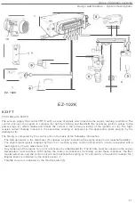
RENIX
-
F
RENIX-F
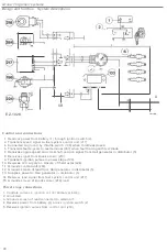
B200K
(The above
illus
tr
a
t
io
n and
t
he
following text
are
based
on
the B
200
K
engine used
in
the 740)
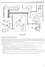
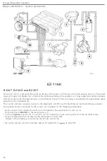
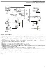
The
sys
tem
consis
t
s o
f
an electronic
co
ntrol
u
nit
(
1
)
whi
ch is supplied
with
engine speed an
d
c
r
anksha
ft
position sig
-
nals
by an
i
ndu
c
tiv
e
speed/position
p
i
c
k
-
up
Th
e
pick
-up
detects
th
e
passage of a number
of
'
te
eth' o
n
the
fly
-
wheel
(
3)
.
The
co
ntro
l
unit
is a
l
so
sup
pli
e
d with
i
nf
or
mation
o
n
eng
in
e
load
through
a vacuum
l
ine (
4
) co
nne
c
ted to
the intak
e
manifold,
the
pressure
in
which
ac
tu
a
te
s
a vacuum advance
un
it
(5) in
tegr
al
with th
e
unit
.
The
s
p
eed and
l
oad signals are
pro
cessed
by
th
e co
ntr
ol
unit
electronics and compa
r
ed
with the timing
se
tt
ings
stored
in
the memory.
Hav
ing
used the
information
t
o compute
the
op
timum
timing
,
the unit
t
ransmi
t
s
co
ntrol
sig-
na
l
s
t
o an
integral power
stage
wh
ich
makes and
breaks
t
he current in
the
primary
w
i
nding of
the
ignition
at
the
correct ins
tant
,
gene
ratin
g a high
-
tension
curren
t
the
secondary
.
The
HT
pulse
fed
to
t
he d
i
s
t
ribu
t
or
(7
)
for
del
ivery
t
o
th
e appropria
t
e spark plug
(81
.
Apart
from the rotor
,
the
distr
i
butor
con
tain
s
no mechanical
or
electronic
co
mponents
,
its
sole
funct
io
n being
to
dis-
tribute the
high
-
tens
ion cur
rent
to
the
co
rre
c
t plug
.
•
At
idl
i
ng
speeds of
less than
1000
r
I
m
in,
the
cont
r
ol u
n
i
t
t
he
t
iming
by
t
o
prevent
a drop
i
n
whe
n
the AC
system
is
sw
itched on or
when a drive
position
i
s selected on
an automat
ic
mod
e
l.
45


