Group
28
Ignition systems
Design and function
System descriptions
II '
t12V
A
0
0
I
5
D
Signels to diegnostic unit
(Picture
0
)
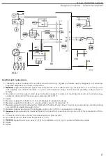
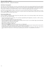
In this mode, the diagnostic
circuit in the control unit
reads the
sele
c
ted test function
program and determines
,
as ap-
propriate
,
which fault/acknowledgement
code is
to be displayed by the LED to report
a
fault
stored in
the
memory or
confirm
operation of
a
switch.
(The arrows
in
th
is
picture indicate that the
direction
of
signal
flow
is
from the
control
unit to the diagnostic unit.)
The
diagnostic
controls the
operation of
the
transistor
.
To produce a flash, the
circuit activates
the tran
-
sistor, connecting
terminal 1
on
the
control unit
to
ground
across terminal
20.
Current
then flows through the
ignition
switch
and diagnostic
unit
to
control unit
terminal 1
and
to
ground across
terminal
20,
causing
the LED to light
(i.e
.
to
produce
one
flash of the particular
digiti
.
Immediately after
this
,
when the LED has been
extinguished
,
the signal
transistor
opens
the terminal 1
ground
c
onnection and the
c
ycle
i
s repeated until
the three-digit
code
for the partic-
ular fault
or acknowledgement code
has been
completed
.
If the self-diagnost
i
c
function
has been
selected
,
the
d
i
agnosti
c
must be suppl
i
ed w
i
th
information on when
the
fault code
i
s
to
be disp
l
ayed
.
The
c
ontrol unit
rece
i
ves this informat
io
n
the form
of the new signal
which
is
initiated
when the
voltage at term
i
nal
1
falls to
zero as pushbutton
A is aga
i
n depressed
.
67


