Group
28
Ignition sys
t
ems
D
esign and function
-
System descript
ions
1
4
1114
,.
"
•
0
0
0
"
,
.
, ,
•
•
"
,
•
,
.
•
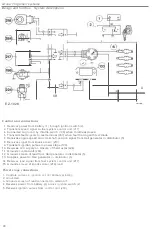
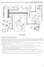
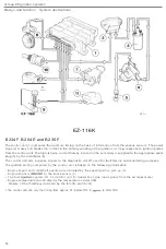
EZ
-
118K
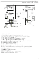
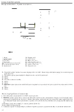
Control unit connections
3. Supplies
fault
indication signals to
te
s
t
terminal
(267)
when
test diode
is con
nected.
4
.
Supplies power to Hall
generator in distributor
(
5
).
6
.
R
eceives supply
from battery
(1) across ignition
switch
(2).
7
.
Grounded by
idling swi
t
ch (272)
when throttle is closed.
9.
R
eceives 12 V
supply
from AC pre
ss
ure
switch (8
1
) and/or idling
compensation
r
elay
(293)
.
1
0
.
Grounds Hall
generator
distributor
(5).
11
.
Grounds temperature
sensor
(273) (
B
230
K
only)
.
12
.
Grounds
kno
c
k
se
nsor
(2
18
)
term
i
n
a
l
2
.
13
.
Receives
signa
ls
from knock
sensor (
218
).
14
.
Grounds fu
el c
ut
-o
ff
solenoid valve
(271)
(
B230K
only)
.
16
.
Supplies ignition pulses
t
o
power
s
ta
ge (
419
)
term
in
alS
.
20. Grounds
con
trol
unit
(
260
).
24.
Rece
ives
engine
sp
ee
d/cran
k
shaft
position
signal
from
H
all gene
r
a
t
or in
distr
i
butor
(5).
25
.
Rece
i
ves engine temperature
signal
from temperature
sensor
(273).
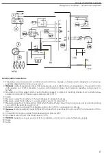
Power stage
connect
i
ons
1
.
Controls
cu
rrent
in
i
gnition
coil (
4
)
pr
im
ary w
i
nding
.
2
.
Grounded
.
3
.
Grounds
screen
of
lead connec
te
d
to
term
i
nalS
.
4
.
Re
ceives
p
o
w
er
from
battery
(
1
)
across ignit
io
n switch
(
2
).
5
.
Recei
ves ig
nition pu
ls
es from
co
ntrol unit
(260).
54

