Group
28
Ignition
systems
Fault tracing
,
EZ-102K
Fault tracing, EZ-102K
HI
Check
secu
r
ity
of ground
leads
at terminals on intake
manifold
(twin
black leads).
V
12 V
15
H2
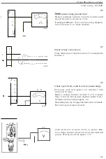
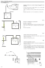
Check LT supply to ignition coil and power
stage
Switch
on
ignition. Measure voltage
between
ignition
coil
terminal 15
and ground. Voltmeter
reading
shou
ld
be approx. 12 V.
If vottage
=
0 V:
Open-circuit in
lead
from central electrical unit. (See
wiring diagram.)
H3
Disconnect power stage
back
con
nector
sleeve and connect
inst
rument
to
rear
of
connec
tor.
Measurement
from
front may dam-
age
terminal
s,
resulting in
loo
seness
and poor contact.
Check
that voltage across each of
connector
terminals
1
and 4 and ground
is
approx.
12
V. Measure individu-
ally between each
terminal
and ground.
1
4
I
I
I
143
I
If vottage
=
0 V
:
Open-circuit
lead
from central electrical unit. (See
wiring diagram,)
Switch off ignition.
137

