Group
28
Ignition systems
Design and function
-
General
0·
1
-10
-20
-30
°
2
1
A
'
0·
Contact-breake
r
versus electronic systems
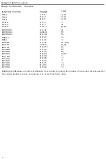
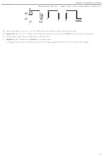
Figure
{AI shows
the tim
ing
curve
for
a
con
tact
-
breaker
ignition system,
wh
i
le
(
BI
illustrates
the
settings
with wh
ich
an electronic system
is
programmed
, i
n the form
of
a three
-
dimensional
map
_
In
each case, both
engine speed and
load are
taken
into
account
when
determining
the
setting
.
However
,
in
co
ntrast with the
electronic system,
which
computes the
t
iming,
the
con
ta
ct-breaker system controls it
w
i
thin a
specified
range
.
The timing must
be
con
trolled
to a high degree
of accuracy
to
meet
the
demands of the modern engine for
the
clean
-
es
t
possib
l
e exhau
s
t
emissions, maximum fuel economy and high performance under
flu
c
tuating
condi
t
ions.
N
either may
the
se
requirements be permitted to
vary, even
following an extended period
of
driving
.
Timing curve
symbols
Both
figures
the manner
in
whi
ch
the t
iming
ang
le {al
varies
w
i
th the
engine speed
(
n) and the va
cu
um
(pi
in
the
in
take
man
i
fo
l
d
.
The
ang
le (a) inc
reases with
speed
;
in
other
word
s, igni
t
ion
of
the fue
l/
a
i
r mixture takes p
l
ace
earlier as the speed rises
.
The
angle
increases
w
i
th the
vacuum in
the
intake manifold
i.e.
as the eng
i
ne load falls
and
the
fuel/air
charge
supplied to the engine becomes
smaller
.
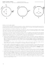
Contact-breaker
ignition systems
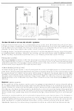
A
. Co
nt
ac
t
-breaker ignition systems
con
trol
the timing with the aid of a
centrif
ugal
governor
(1)
and a vacuum ad-
vance
un
i
t
(2). (Being a speed
-
dependent device
,
the
governor advances the ignition as the
spee
d
increases
,
while
the
vacuum advance
unit
retards
it
as the
engine
load
increases
response to the vacuum signal from the
in
take
manifold
.)
T
he two devices
operate independently
w
i
thin a
tol
erance
band
of
approx
.
Overall
,
this means that
the system controls the tim
in
g with
i
n a to
l
eran
ce
range
of approx.
since
the
setting is
the
sum of
the angles
in-
dicated
by the two
curves.
Furthermore
,
the
variat
i
on
wh
ich
results
from
wear
of
the
breaker
points
the
over-
all
t
iming.
ignition
systems
:
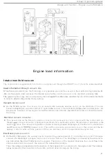
B
.
The
co
ntrol
unit
(
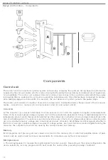
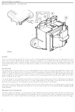
3) of an electron
ic
ignit
i
on
system,
by
i
s programmed w
i
th a
series
of specific settings
f
or a
number
of defined speeds and engine loads
.
This means that the timing
can
be controlled
to
an accuracy as
h
igh 8S 8
fraction
of a degree and tha
t
each
ignit
io
n
pulse
is
de
l
ivered as close as
pos
sib
l
e
t
o
the
op
ti
mum
point.
(
Thi
s
high
level of accuracy is achieved partly by the fact that the
con
trol
unit
interpola
te
s
between
the
programmed
speed and load points
.
In other words
,
it
is capable of computing
an intermediate setting.) Furthermore
,
the timing
can be
com
put
ed
over a wider range and is not restricted by the type
of
linear functions typ
ic
al
of
a
centrifugal
gov
-
ernor
.
The
t
iming is computed
with th
e
a
i
d
o
f
sensors
wh
ich
determine
the
engine load and speed.
Th
is in
format
io
n
is
transmitted electrically t
o
the
control unit electronics
,
in
wh
ic
h details
o
f
a number of
d
i
fferent
speed
and load
com-
binations
,
together with the
appropriate
t
iming se
tt
ings,
are
s
tored
.
to
each
igni
t
i
on pulse
,
the
control
unit
com-
putes a setting wh
ic
h
is
perfectly mat
c
hed to the
engine running
co
nd
i
tion
s
prevailing at
the precise instant
.
Adjustments
required by the various timing
co
mpensation fun
c
tions are
added
to the three
-
dimensional map.
13


