53
Installation Instructions VRC 630 0020095108_00
Operating the controller 7
7.2.5 Menu
5:
Setting the set-back temperature,
heating curve and hot water temperature
( cylinder target)
Set the set-back temperature, heating curve and hot
water temperature in Menu
5
.
Setting the set-back temperature and the heating
curve
HK1
5
Parameters
Set-back temperature
15 °C
Heating curve
1,2
>Select target room temperature
Settable
parameters
Description
Setting range
Factory
setting
Set-back tempera-
ture
Temperature to which the heating is regulated during the set-
back period (e.g., overnight)
Can be set separately for each heating circuit
–
–
5 °C ... 30 °C
15 °C
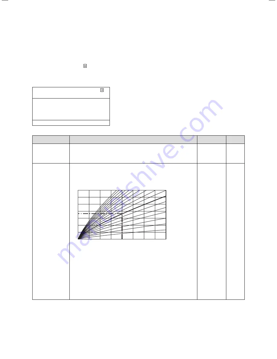
Heating curve
The heating curve represents the relationship between external
temperature and the flow temperature.
Max Flow Setpoint.
Outside temperature in °C
in °C
90
80
70
60
50
40
30
20
20
15
10
5
0
-5
-10
-15
-20
1.5
4.0 3.5 3.0
2.5
2.0
Heating curves
1.2
1.0
0.6
0.2
(
¬ Chap. 3.4
).
Setting is made separately for each heating circuit.
The room temperature of your heating installation depends to a
great extent on the selection of the right heating curve. If the
selected heating curve is too high, the temperatures in the hea-
ting installation will also be too high, resulting in higher energy
consumption.
If the selected heating curve is too low, the desired temperature
level may only be reached after a while or not reached at all.
–
–
–
–
0.1 ... 4.0
1.2
Table 7.5
Set-back temperature and heating curve
Inform the owner about the optimum settings.
>
Содержание VRC 630
Страница 1: ...GB VRC 630 3 ...
Страница 2: ......
Страница 54: ......
Страница 55: ...For the heating engineer Installation Manual VRC 630 ...
Страница 145: ...91 Installation Instructions VRC 630 0020095108_00 Appendix Declaration of conformity Fig A 1 Declaration of conformity ...
Страница 152: ...0020095108_00 GB 022010 Subject to alterations ...


