Key
VR 32
VR 32 bus coupler
VR 60
VR 60 mixer module
BUS eBUS
WW DHW
cylinder
ZIR Circulation
pump
SP
Cylinder sensor
KW
Cold water
VF 1
Flow temperature sensor
VF 2
Flow temperature sensor, Heating circuit 2
VF 3
Flow temperature sensor, Heating circuit 3
VFa
Flow temperature sensor, Mixer circuit a
VFb
Flow temperature sensor, Mixer circuit b
HK 1-P
Pump for direct circuit
HK 2-P Pump for heating circuit 2
HK 3-P Pump for heating circuit 3
HKa-P
Heating pump for mixer circuit
HKb-P
Heating pump for mixer circuit
HK 2
Mixer for heating circuit 2
HK 3
Mixer for heating circuit 3
HK a
Mixer for mixer circuit a
HK b
Mixer for mixer circuit b
LP/UV1 cylinder charging pump/Diverter valve
i
Caution - illustration shows principle only!
This system schematic does not include all
the shut-off and safety devices necessary for
professional assembly. System-specific plan-
ning is required!
You can connect the first boiler directly to the eBUS on
the controller. Note the polarity when doing this.
From the second boiler onwards, a bus coupler is neces-
sary.
230V~
N
L
9
RT 24V=
BUS
Anl.-
Therm.
8
7
+
-
5
RT 230V~
4
3
1
2
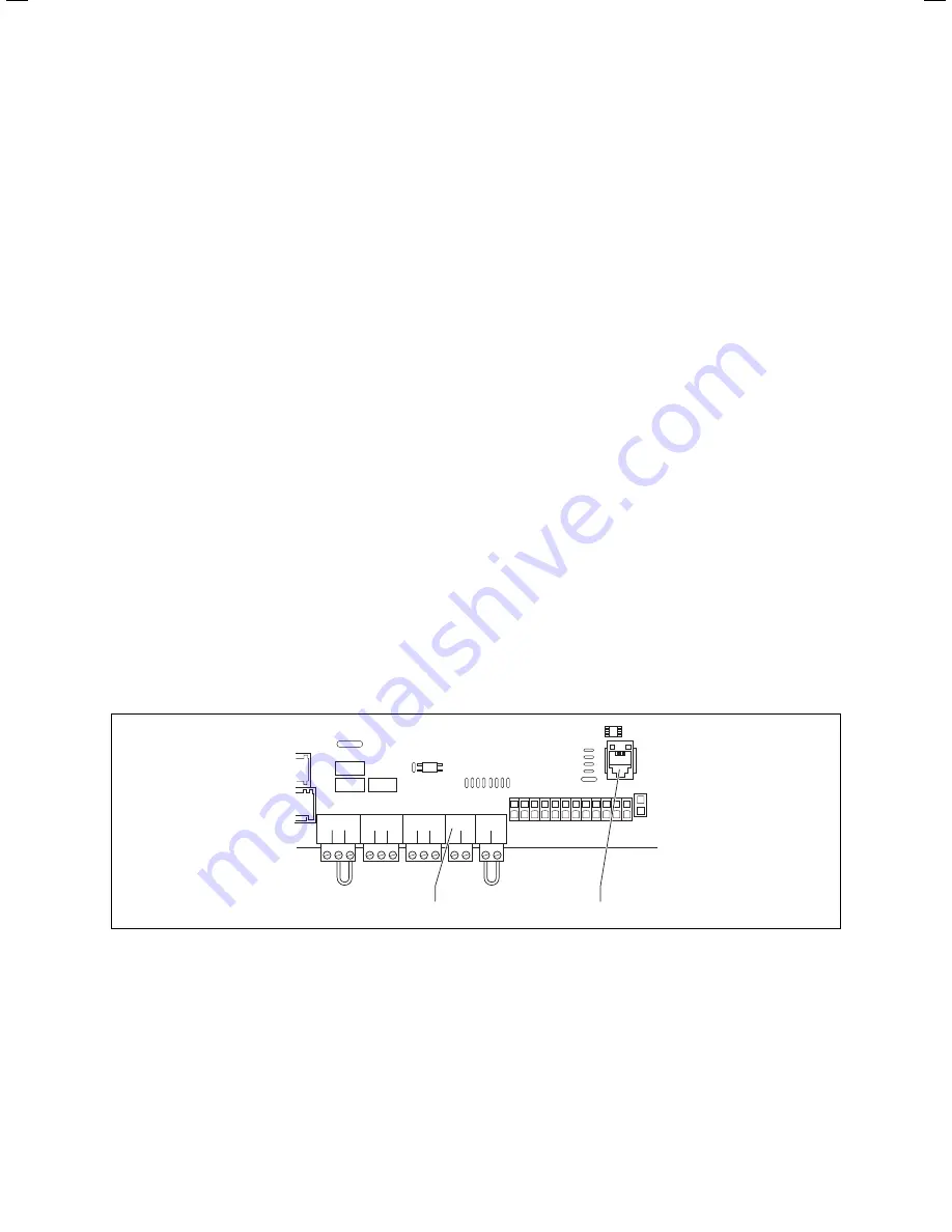
Fig. 5.7 E-box for connecting the VR 32 bus coupler
Key
1 eBUS interface to the VR 32 bus coupler
2 eBUS (only use without the VR 32 for the first boiler)
Take note of the VR 32 bus coupler manual.
>
35
Installation Instructions VRC 630 0020095108_00
Electrical installation 5
Содержание VRC 630
Страница 1: ...GB VRC 630 3 ...
Страница 2: ......
Страница 54: ......
Страница 55: ...For the heating engineer Installation Manual VRC 630 ...
Страница 145: ...91 Installation Instructions VRC 630 0020095108_00 Appendix Declaration of conformity Fig A 1 Declaration of conformity ...
Страница 152: ...0020095108_00 GB 022010 Subject to alterations ...


