85
Installation Instructions VRC 630 0020095108_00
De-commissioning 10
If the controller is mounted on the wall:
e
Danger!
Danger to life from live connections!
The mains switch does not disconnect the
power supply completely.
Switch the power supply off before wor-
king on the unit.
Secure the power supply against being
switched on again.
2
1
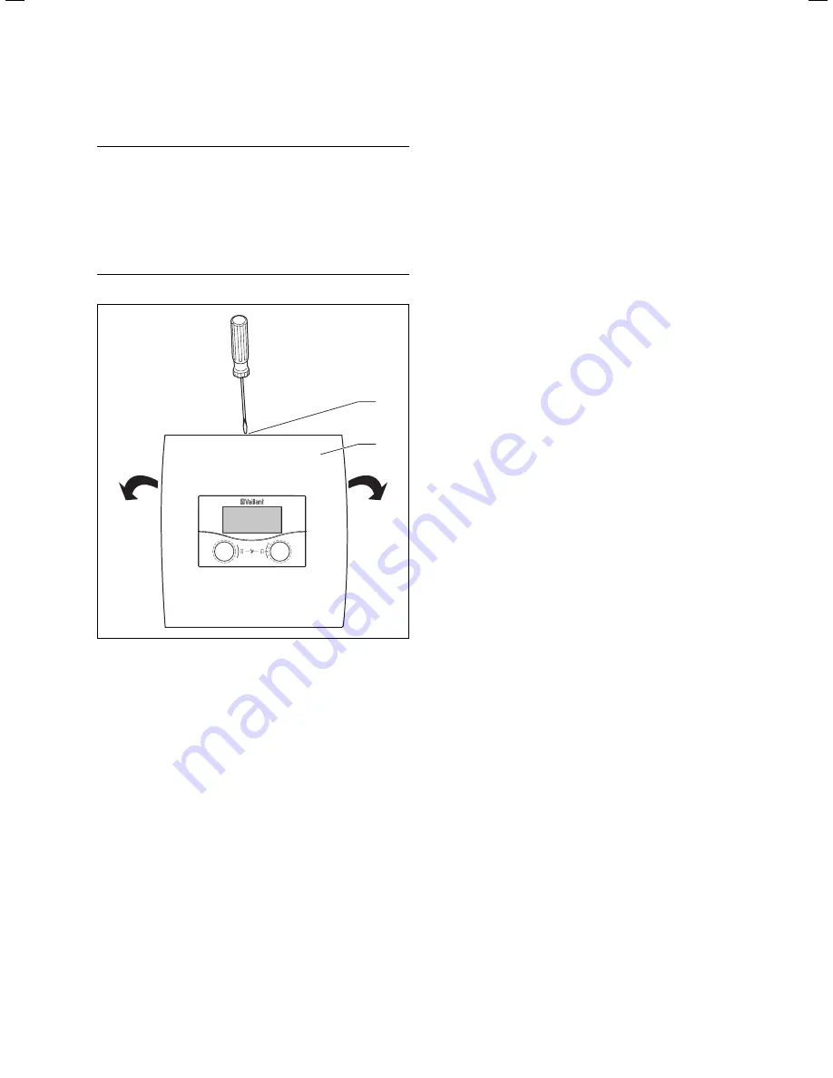
Fig. 10.2 Opening the wall mount
Key
1 Screw
2 Housing
cover
The housing cover comprises a single part.
Loosen the screw (
1
) on the upper side of the wall
mount.
Flap the housing cover (
2
) downwards. Take the hou-
sing cover off its hinge and remove it.
Pull the controller (
1
) from the wall mount (
2
).
Insert a screwdriver into the two retainer straps to do
this (
¬ Fig. 10.2
).
Unfasten and remove the eBUS cable from the termi-
nal strip on the controller.
Unfasten and remove the cable for the external sen-
sor.
Unscrew the wall mount from the wall.
Plug the holes in the wall if necessary.
>
>
>
>
>
>
>
>
>
If the controller is fitted in the remote control unit:
Remove the housing cover from the remote control
unit.
Carefully remove the controller from the wall base.
Remove the connecting cable.
Remove the wall base if necessary.
Plug the holes in the wall if necessary.
10.3 Disposing
of
the
controller
Neither the controller or any of its accessories belong in
the household waste.
Dispose of the old unit and any accessories professio-
nally.
>
>
>
>
>
Содержание VRC 630
Страница 1: ...GB VRC 630 3 ...
Страница 2: ......
Страница 54: ......
Страница 55: ...For the heating engineer Installation Manual VRC 630 ...
Страница 145: ...91 Installation Instructions VRC 630 0020095108_00 Appendix Declaration of conformity Fig A 1 Declaration of conformity ...
Страница 152: ...0020095108_00 GB 022010 Subject to alterations ...


