5
4
2
3
2
1
3
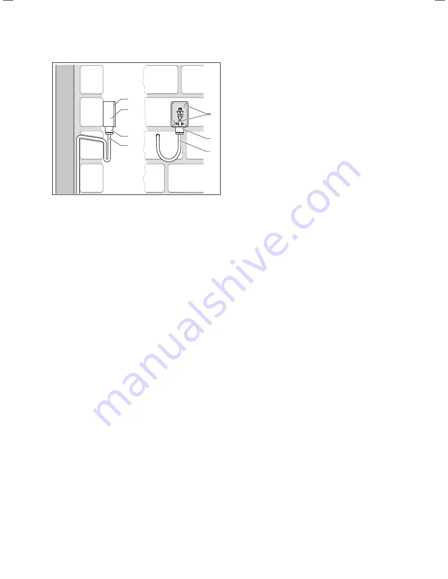
Fig. 4.9 Installation of the VRC 693 external sensor
Key
1 Mounting
apertures
2 Cap nut for cable entry point
3 2-core connecting cable with loop to catch drips
4 Casing
5 Housing
cover
Carefully plan any holes required for fixing and cable
routing before drilling them.
Observe the requirements for the installation location
(
¬Chap. 4.7
)
Remove the casing cover (
5
) from the external sen-
sor.
Mark the position on the wall. Observe the cable rou-
ting for the external sensor.
Drill two holes 6 mm diameter to match the fixing
apertures (
1
).
Insert the wall plugs supplied.
Route the connection cable (
3
) on the customer side
with a slight incline to the outside and with a loop to
catch drips.
Fix the housing (
4
) with 2 screws through the fixing
holes (
1
).
Run the connecting cable on the customer side (
3
),
using cable of at least 2 x 0.75 mm2 cross-section.
Pull the connecting cable in through the cable entry
(
2
) from below.
By careful work and by appropriate cable routing,
ensure that the outside sensor and the building are
both water-tight.
The electrical installation is carried out as described
in Chapter 5.4.
Make sure that the seal is correctly seated in the
cover of the housing (
5
).
Press the cover (
5
) on to the housing (
4
).
Fix the cover (
5
) to the housing (
4
) with the screws
supplied.
>
>
>
>
>
>
>
>
>
>
>
>
>
>
>
26
Installation Instructions VRC 630 0020095108_00
4 Assembly
Содержание VRC 630
Страница 1: ...GB VRC 630 3 ...
Страница 2: ......
Страница 54: ......
Страница 55: ...For the heating engineer Installation Manual VRC 630 ...
Страница 145: ...91 Installation Instructions VRC 630 0020095108_00 Appendix Declaration of conformity Fig A 1 Declaration of conformity ...
Страница 152: ...0020095108_00 GB 022010 Subject to alterations ...


