


1-12
DVW-250/250P
1-5. Removal/Installation of Cabinet
c
Be sure to turn the power off, and remove the power cord and/or battery.
Battery Case
1.
Remove the top panel and bottom plate.
2.
Disconnect the connector CN915 and fasten terminal CN932 on the MB-601 board.
(CN932 disconnection : Pinch the terminal and pulled out.)
3.
Remove the four screws and pull out the battery case.
4.
Disconnect the fasten terminal from the connector CN422 on the FU-64 board.
5.
Remove the battery case from the unit.
Top Panel
Loosen the four coin screws and move the top panel in the direction of the arrow.
Front Cover
Loosen the two screws and remove the front cover from the unit.
Front Panel
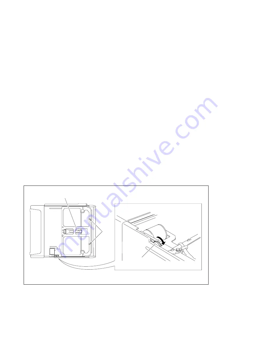
1.
Remove the front cover.
2.
While lifting up the C lock arm of the cassette compartment, turn the gear (red) in the direction of
the arrow to slide the cassette compartment 10 to 20 mm. Remove the two screws and the two
washers through the holes (* mark) as shown in the figure.
n
At this time, the two washer are out from the front panel, do not lose them.
3.
Remove the three screws from the front panel.
4.
Remove the four volume knobs and remove the front panel from the unit.
At this time, the switch covers are out from the front panel, do not lose them.
Notes during installation
After attaching the front panel, check the switch covers are attached with it.
1-5. Removal/Installation of Cabinet
C lock arm
*
Gear (red)


