43
d 16
Driver preparation completion. This contactor shall be CLOSED if no fault was detected after motor drive
power is supplied.
d 17
Fwd run direction reference. When inverter is in fwd run, delay reference time shall be in accordance with
setting in Parameter3-03, and contactor shall be CLOSED when time met. Relay shall be interrupted when
inverter stops or is switched to Rev run stations. Attention shall be paid that counting here shall begin from
Fwd run.
d 18
Rev run direction reference. When inverter is in Rev run, delay reference time shall be in accordance with
setting in Parameter3-03, and contactor shall be CLOSED when time met. Relay shall be interrupted when
inverter stops or is switched to Fwd run stations. Attention shall be paid that counting here shall begin from
Rev run.
d 19
Fwd/ Rev run direction reference. This reference shall be available at switching of Fwd/Rev run. Description
of action: During direction switching of motor drive, the relay shall be Opened and then delayed in a time
complied with setting in 3-03 and 3-04. After delay, the relay shall be closed. Provided that delay setting in
3-03 and 3-04 is 0, relay shall be kept in closed condition and not open until machine stop signal appears.
Notes: 1.“CLOSED” mentioned above refers to closing of normally open contactor(RA-RC), and normally
closed contactor(RB-RC) shall open simultaneously; while “open” shall refer to opening of
normally open contactor(RA-RC), and normally closed contactor(RB-RC) shall be closed
simultaneously.
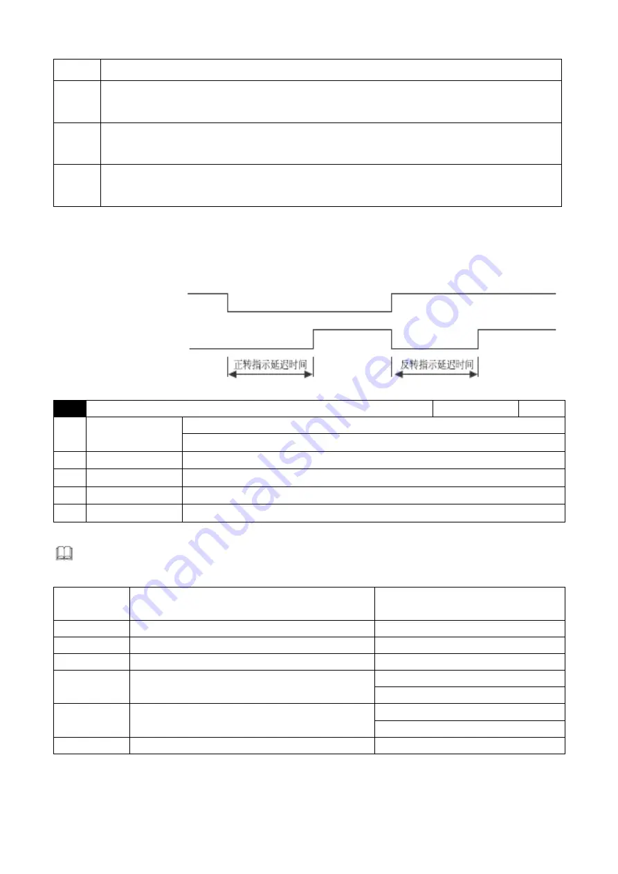
2.When it is set to d17, d18 and d19, once stop signal appears, relay shall be interrupted
immediately. See sequence diagram below:
Fwd and rev run stations
0: Fwd run 1: Rev Run
Relay output
0: Open 1: Closed
3-06
Analog output frequency/current signal setting
Factory setting
0
Setting range
0: output frequency 1 (before slip compensation)
1: output frequency 2 (after slip compensation)
2: Analog current meter(0 to 250% of rated current)
3: output voltage
4: DC bus voltage
5: consumed power
This parameter select AC motor driver signal voltage (0 to +10V) to output the corresponding
content, which is as shown in table below:
Setting value
Analog content
Max. value of output voltage
corresponds to :
0
Output frequency 1 (before slip compensation)
Highest operation frequency
(
1-00
)
1
Output frequency 2 (after slip compensation)
Highest operation frequency
(
1-00
)
2
Output current
250% rated current
3
Output voltage
220V series:250V
440V series: 500V
4
Bus voltage
220V series:500V
440V series: 1000V
5
Consumed power
200% inverter rated output
Fwd run reference delay time
Rev run reference delay time


