54
When deceleration is performed, back-up energy may be generated in AC motor drive due to inertia
of motor load, and DC side voltage may rise to max value. Thus, when over voltage stall prevention
is started, over voltage at DC side shall be detected, and deceleration shall be interrupted (output
frequency shall be kept), which will not be performed again by AC motor drive until voltage is below
setting value.
Techniques Forum
This function is set for uncertain load inertia circumstances. Deceleration over voltage shall not
occur in normal load stop, and deceleration time shall also be applicable. However, tripping shall not
occur due to over voltage in occasional load back up inertia increase stop; in these occasions,
deceleration time shall be increased automatically by the inverter to stop. This function is
inapplicable provided that deceleration time disturbs application. This problem shall be solved by
increasing deceleration time or install braking resistor to absorb excessive back up voltage.
6-01
Over current stall prevention level setting
Factory setting
d 170
Setting
range
d 0
Unavailable
d 1
d 20<->d 200%
UNIT
1%
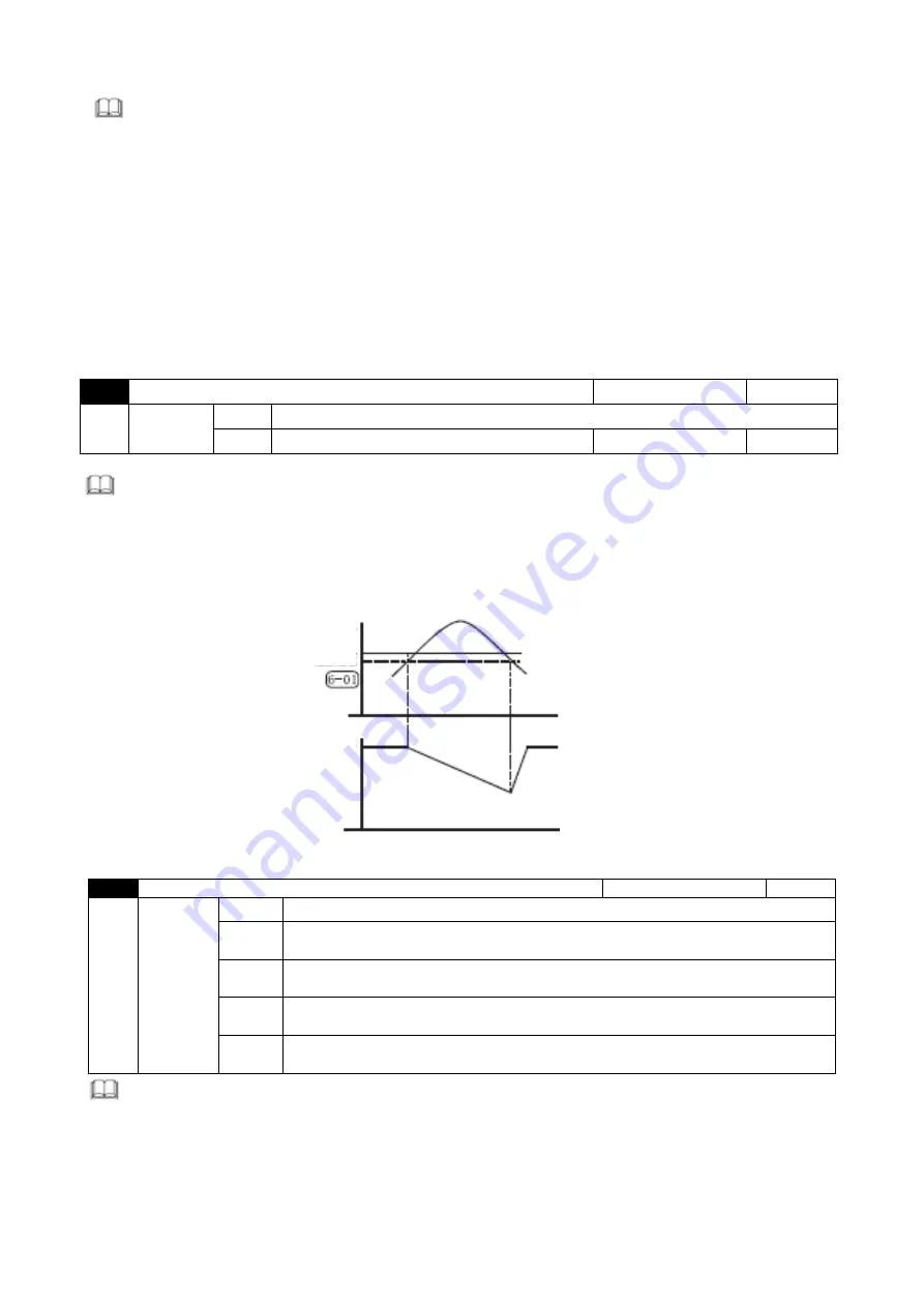
During operation of AC motor drive, provided that output current exceeds set value of 6-01 (Over
current stall prevention current level during running), output frequency shall be decreased by AC
motor drive to prevent motor stalling. AC motor drive shall perform acceleration again to set
frequency when output current is below setting of 6-01. Set unit shall be percentage of rated
output current (100%) of the AC motor drive.
6-02
Over-torque detection function option
Factory setting
d 0
Setting
range
d 0
No detection
d 1
Over torque detection (oL2) during constant speed running, continue
to run after detection.
d 2
Over torque detection (oL2) during constant speed running, stop running
after detection.
d 3
Over torque detection (oL2) during acceleration, continue to run after
detection.
d 4
Over torque detection (oL2) during acceleration, stop running after
detection.
when this parameter sets the action of driver when OL2 actuates, no action when set as 0. When set
as other values, the manipulator will display OL2 error when OL2 actuates. 1 or 3 setting shows that
the inverter continues to operate after error occurs. The rest of OL2 error needs to its automatic
reset after the error disappears or stop the inverter and reset error simultaneously. 2 or 4 setting
indicates that the inverter stops operating after error happens. Press RESET key to reset OL2 error
after 5 seconds. Determine whether setting this function at constant speed or accelerated speed is
more effective according to the actual usage.
Output Current
Stalling over current
detection level
Output frequency
Time
Time
Over current stall prevention function during running


