30
Service Manual – SW5500, FLOORTEC R 985
05 - Control System
Functional Description
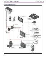
The machine is started by the ignition key (KEY),
located on the main control panel When the key is
turned to I, the Display Controller (EB3) is powered
which in turn powers the control section of the Main
Machine Controller (EB1) via the output on J1 5
The Main Machine Controller (EB1) in turn powers
the control section of the Drive Wheel Controller
(EB2) via the output on J1 11
Ahead of the ignition key (KEY) there is the
emergency button (SW0) Upline of SW0 the key
circuit is protected by the relevant fuse (F2)
Between the fuse (F2) and the emergency button
(SW0) is the normally closed contact of the shut-
off relay inside the battery charger This contact
prevents machine operation when the battery
charger is connected to the mains If there is no
battery charger, the contact is short circuited by a
jumper on connector (C2)
Following the starting procedure described above
using the (KEY), both boards (EB1) and (EB2), after
checking the status of the outputs to check whether
there are any internal or external short circuits,
power the corresponding contactors (ES1) and (ES2),
which supply battery voltage to the corresponding
power sections of the boards themselves
Checking of the various machine functions occurs
via momentary buttons on the Main Control Board
(EB4) (on the steering column) and side control
panel ì board (EB5) (beside the seat)
All machine functions, with the exception of the
drive, are managed and controlled directly by the
Main Machine Controller (EB1)
The drive function is managed by the Drive Wheel
Controller (EB2)
All controls relating to the drive function (operator
presence (SW1) and accelerator pedal (R1)) are wired
directly to the Drive Wheel Controller (EB2), with
the exception of the following 2 control signals:
• Digital forwards/backwards signal
• Analogue maximum speed signal
The digital forwards/backwards signal is managed
by the Main Machine Controller (EB1) which
receives the control from the reverse button
and is sent to the Drive Wheel Controller (EB2) via
output A4 1
The horn and the reverse warning buzzer are an
integral part of the Main Machine Controller (EB1)
The analogue maximum speed signal is managed
by the Main Machine Controller (EB1) on the basis
of the status of various inputs and parameters (see
chapter) and is sent via
output A4 3 to the Drive Wheel Controller (EB2)
The Drive Wheel Controller (EB2) communicate with
the Main Machine Controller (EB1) also with CAN-
BUS (see
On the Main Machine Controller is installed a 3-axis
accelerometer that is used to reduce the speed of the
machine during the turns (see
) and to alert the operator when he

