


123
Service Manual – SW5500, FLOORTEC R 985
24 - Electrical System
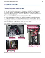
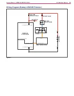
Functional Description - Battery Version
The electrical system is basically a 24Vdc nominal system of electronically managed motors
The battery is connected to the system by means of the connector (C1) Downline of the connector a safety
fuse is installed, (F1) before the power section of the Main Machine Controller (EB1), and (F3) before the
power system of the Drive Wheel Controller (EB2) These fuses are sized to blow only if the power section of
the boards becomes seriously damaged
The key circuit, independent of the previous ones, is protected by the fuse (F2)
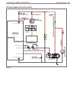
The on board battery charger (CH) is directly connected on the battery pins for the power side, to connector
(C2) for the inhibition signal When the battery charger is not connected to the electrical mains, the relay
inside the battery charger closes the contact between the 2 wires connected to (C2), this contact opens when
the battery charger is connected to the electrical mains When the battery charger is not installed, the
connector (C2) is closed by a jump connection The connector contacts (C2) are upstream of the ignition key
(SW0) and cut off the power supply to all control section of the electrical system
For further details, see the descriptions of individual sub-systems
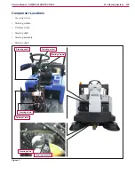
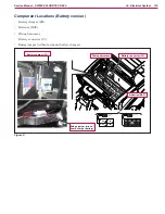
Figure 1:
Battery (BAT)
Connector (C1)
Main Machine Controller fuse (F1)
Key circuit fuse (F2)
Drive board fuse
(F3)
Drive Wheel
Controller (EB2)
Main Machine Controller
(EB1)