


74
Service Manual – SW5500, FLOORTEC R 985
05 - Control System
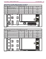
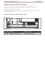
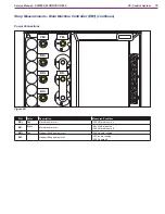
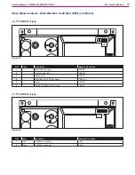
Shop Measurements - Main Machine Controller (EB1) (continues)
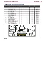
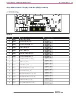
J1: Signal inputs connections
J1
Figure 46:
J1
PIN
Color
Description
Measured/Condition
1
Oange
Return from KEY circuit
Key Off - 0.02V
Key On -23.9V
2
Red/White
HOPPER ENABLING button input
Pressed - 24.8V
Not pressed - 0.01V
3
Balck/White
Headlight button input
Pressed - 24.8V
Not pressed - 0.01V
4
Pink
WATER PUMP button input
Pressed - 24.8V
Not pressed - 0.01V
5
Green
LIFTED HOPPER input
Down - 0.008V
Up - 22.8V (Illuminated)
6
Blue
HOPPER POSITION input
Down - 0.008V
Up - 22.8V (Illuminated)
7
-
8
Brown/Black
FUEL RESERVE input (Engine Only)
LPG 4.99V fuel OK 0.006 Low pressure
9
Green/White
Signal power supply
23.4V
10
Blue/White
Signal power supply
23.4V
11
Orange/
Black
Drive Wheel Controller enabling
Key On - 23.9V
Key off - 0.02V
12
Brown
BROOM WEAR input
Normal Broom - 0.009V
Worn out Broom - 22.8V (Illuuminated)
13
Pink/Black
RECTIFIER TEMP. input (Engine Only)
Normal Temp. 0.0V
Excessive Temp 4.9V
14
Red/Black
ALTERNATOR input (Engine Only)
Engine OFF - 0.075V
Cranking - 6V
Engine Running (High Speed) -25.5V
15
Violet
DUMPED HOPPER input
Dumped - 0.01V
Normal - 22.5V
16
Blue/Black
BAT CHARGER DISAB input (NO) (Engine Only with
Hybrid System)
Not measured. Expect 0V for normal operation, Battery
voltage when charger is plugged in.
17
18
Yellow
LOW ENGINE OIL input (Engine Only)
Oil level okay - 4.9V Key Off Engine On
19
Violet/White
Signal power supply
23.4V
20
Brown/White
Signal power supply
23.4V