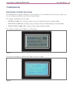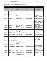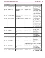
33
Service Manual – SW5500, FLOORTEC R 985
05 - Control System
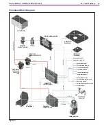
Wiring Diagram
B+
J1.11
J4.2
J4.1
A1.2
J1.3
A1.6
J1.2
J1.4
J2.7
J3.1
J3.2
J3.4
J1.1
Electromagnetic switch
Electromagnetic switch output -
ENGINE VERS. CONFIG. input
HEADLIGHT push-button input
End-of-stroke microswitch power supply
HOPPER ENABLING push-button input
WATER PUMP push-button input
WATER PUMP warning light output
Return from KEY circuit
J1.2
J1.1 Power +
J1.1
30/1
0V
15
50
15/54
30
J2
16
J1.3
J1.4
J1.5
Power -
Power supply enabling
J1.2
P16
P0 P1 P2
P17
P18
LD1
J1.3
J1.4
J1.5
J2.12
J2.15
J2.8
J2.4
Common power signal output
Common power signal output
Working light output
Horn output
B-
Drive system board enabling
BUZZER (BZ)
BEACON LIGHT (BE)
HORN RELAY (ES9)
HORN RELAY (ES9)
KEY CIRCUIT FUSE (F2)
HORN FUSE (F8)
HORN (HN)
WORKING LIGHT (L1)
EMERGENCY
PUSH-BUTTON (SW0)
B
BATTERY -
RESISTANCE
KEY (KEY)
Main Control B. serial connection
Main Control B. serial connection
Main Control B. el. board power supply -
Main Control B. serial conn
Main Control B. serial connection -
Main machine controller power supply -
Main machine controller power
MAIN MACHINE
CONTROLLER (EB1)
DISPLAY CONTROLLER (EB3)
MAIN MACHINE
CONTROLLER
CONTACTOR
(ES1)
MAIN MACHINE
CONTROLLER FUSE (F1)
MAIN CONTROL
BOARD (EB4)
SIDE CONTROL
BOARD (EB5)
MAIN MACHINE
CONTROLLER CONTACTOR
(ES1)
Figure 3:

