75
Service Manual – SW5500, FLOORTEC R 985
05 - Control System
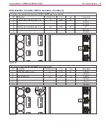
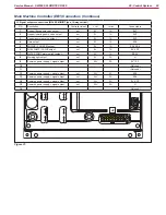
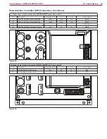
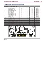
Shop Measurements - Main Machine Controller (EB1) (continues)
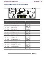
J2: Signal outputs connections
J2
Figure 47:
J2
PIN
Color
Description
Measured/Condition
1
Blue/Black
Hopper lifting pump valve output
Off - 25.2V
On - 0.33V
2
Brown/Black
Hopper lowering pump valve output
Off - 25.2V
On - 0.6V
3
Green/Black
Hopper dumping valve output
Off - 25.2V
On - 0.6V
4
Violet/Black
Horn Relay output
Off - 25V
ON - 0.02V
5
Grey/Black
Control for ENGINE FAN, Speed request and
Charging output relay (Engine Only)
25.09V Off
0.15V On
6
Pink/Black
LPG - Starter relay and LPG safety shut down
solenoid.
FUEL PUMP / VALVE output (Engine Only)
LPG - Key on Initial 0.0V
LPG - Key on after 10 seconds without Alternator
output - 23.9V
EV4, P2
7
Black
WATER PUMP warning light output
Off - 24.3V
On - 0.008V
8
Yellow/Black
Working light output
L1
9
Red
Common power signal output
25.2V
10
11
12
Violet
Common power signal output
25.1V
13
Pink/Black
Common power signal output (LPG Only)
ES4
14
Red/Black
Common power signal output (Engine Only)
LPG - Key on- 24.5V
EV4, P2
15
Violet
Common power signal output
25.1V
16
Blue/Black

