167
Service Manual – SW5500, FLOORTEC R 985
29 - Engine System, LPG
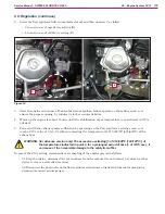
Wiring Diagram
0V
J2.6
FUEL PUMP / VALVE output
J2.14
Common power signal output
J2.5
ENGINE RPM/FAN output
J1.18
LOW ENGINE OIL input
J2.13
Common power signal output
0V
30/1
15
50
15/54
30
P0 P1 P2
ENGINE START RELAY (ES3)
ENGINE START
RELAY (ES3)
ENGINE IGNITION
COIL (EB7)
ENGINE
ECM (EB6)
ENGINE RPM RELAY (ES4)
ENGINE RPM
RELAY (ES4)
CHARGING COIL
SPARK PLUG
BATTERY FUSE (F0)
OIL ALERT
SENSOR (S7)
LPG ENGINE
BATTERIES (BAT)
ENGINE START RELAY (ES5)
ENGINE START RELAY (ES5)
STARTER
ENGINE FUSE
KEY CIRCUIT FUSE (F2)
EMERGENCY
PUSH-BUTTON (SW0)
KEY (KEY)
FUEL SOLENOID VALVE (EV4)
ENGINE START FUSE (F6)
B+ Main machine controller power
B- Main machine controller power supply -
MAIN MACHINE
CONTROLLER (EB1)
Figure 2:


