


72
Service Manual – SW5500, FLOORTEC R 985
05 - Control System
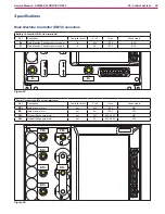
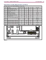
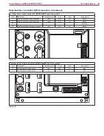
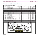
Shop Measurements - Main Machine Controller (EB1) (continues)
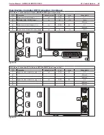
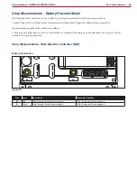
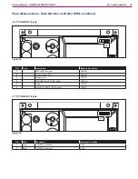
A1: Actuator 1 connection
A1
Figure 42:
A1
PIN
Color
Description
Measured/Condition
1
Red
Main broom actuator /- ()
Up 0.01V
Down 25.1V
Off 0.0V
2
Red/Black
Configuration - Battery or Engine
0.004V when loop is present
3
4
Black
Main broom actuator supply -/+ (1)
Up 25.1V
Down 0.1V
Off 0.0V 1
5
6
Red/Black
Configuration - Battery or Engine
0.004V when loop is present
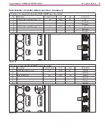
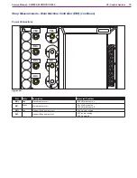
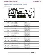
A2: Actuator 2 connection
A2
Figure 43:
A2
PIN
Color
Description
Measured/Condition
1
Red
Right side broom actuator /- (1)
Up 0.18V
Down 25.2V
Off 0.0V
2
3
4
Black
Right side broom actuator supply -/+ (1)
Up 25.1V
Down 0.04V
Off 0.0V
5
6