


102
Service Manual – SW5500, FLOORTEC R 985
20 - Wheel System, Traction
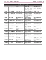
Drive Board Connectors
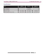
Power Connections (male screw terminals M 6)
Ref.
Description
Drive board
in/out
V ref.
I max.
Connected to
BF
Drive board power
in
24Vdc
250A
ES2
B+
Board power (downline of fuse F3)
in
24Vdc
250A
F3
B-
Drive board power supply -
in
0Vdc
250A
BAT-
U
Drive motor phase U
out
0 - 24Vac
250A
M0.U
V
Drive motor phase V
out
0 - 24Vac
250A
M0.V
W
Drive motor phase W
out
0 - 24Vac
250A
M0.W
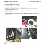
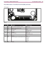
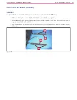
Shop Measurements - Drive Wheel Controller (EB2)
JB Connector:
JB
Figure 7:
PIN
Color
Description
Measured/Condition
1
2
Red
Power Supply from ES2 contactor
Key off - 0v
Key on - 25.3V
3
4
Yellow
Drive Pedal Micro-switch input
Pedal not pressed -0V
Pedal pressed - 23.9V
5
6
Orange/
Black
ES2 Contactor Coil control
On - 0.82V
7
8
Grey
Drive Direction Request
Forward - 0.0V
Reverse - 6.9V