91
Service Manual – SW5500, FLOORTEC R 985
20 - Wheel System, Traction
Functional Description
The main drive components are the steered driving
wheel assembly, the accelerator pedal (R1) and the
Drive Wheel Controller (EB2)
The direction of travel is set with the button on the
Main Control Board: when the machine is started,
it is always set to forward movement Pressing the
reverse button
sets the direction of travel to
reverse, and the reversing buzzer (BZ) begins to
sound until forward movement is selected again
The driving wheel is fitted with a three-phase
electric motor (M0) which is powered by the Drive
Wheel Controller (EB2)
The Drive Wheel Controller (EB2) is powered
through the Drive Wheel Controller contactor (ES2)
The Drive Wheel Controller contactor (ES2) is
activated by the same board, after the initial check
on the conditions of the inputs and outputs, when it
receives the start-up signal from the ignition switch
circuit (KEY) via the relay (ES8)
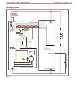
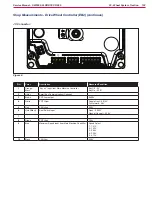
The main control inputs of the Drive Wheel
Controller (EB2) are composed of:
Analogue signal from hall sensor on accelerator
pedal (R1)
Digital signal from safety microswitch inside
accelerator
pedal (R1) (open only in rest position)
Digital signal from seat operator presence
microswitch (SW1)
Frequency signal of the drive motor (M0) encoder
(ENC)
Analogue maximum machine speed setting signal
from the Main Machine Controller (EB1)
Digital forward/reverse drive signal from the Main
Machine Controller (EB1)
Digital signal from drive motor temperature sensor
(S5)
The drive system is disabled when the seat
microswitch (SW1) does not detect the operator on
the driver’s seat, while when the hopper open sensor
(S1) detects that the hopper is lifted, the maximum
machine speed is decreased to a safety value
When the machine is started with the key switch
(KEY), the system is always placed in forward mode
Pressing the reverse button changes to reverse mode
until the button is pressed again When reverse is
selected, this is signalled by the icon on the display
and the buzzer
The position of the accelerator pedal (R1) determines
the machine speed The safety condition for drive
system activation is that the accelerator pedal (R1)
is totally released when the system is turned on with
the ignition switch (KEY)
The drive motor encoder (ENC) provides feedback
of the real speed of the motor with two 90° shifted
square signals
The voltage levels corresponding to the accelerator
released and fully depressed positions are acquired
by the drive board via a dedicated procedure; if this
is not performed, the default values of 0 1V and
5 0V, respectively, are used
If the drive motor temperature sensor (S5) is open
(motor temperature over 150° C) the drive speed is
reduced to about 23%
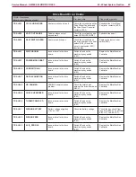
If the Drive Wheel Controller (EB2) detects a
fault with the drive system, this is signalled via
an error code on the Display Controller (EB3) in
the form “ALARM Traction XXX”, where XXX is a
2- or 3-digit number The alarm is communicated
by the Drive Wheel Controller (EB2) to the Main
Machine Controller (EB1) to be shown on the display
using the CANOPEN protocol on the CAN-BUS
line between connector J7 of the Main Machine
Controller (EB1) and connector JC of the Drive
Wheel Controller (EB2)
The CAN-BUS is also used to transfer from the
drive board to the Main Machine Controller the
information about the movement of the machine
This information is used by the Main Machine
Controller to start and stop the brooms and vacuum
motors


