background image

12. WHEN USING WITH A GENERAL-PURPOSE INTERFACE 

12 -  79 


(c)  Operation 

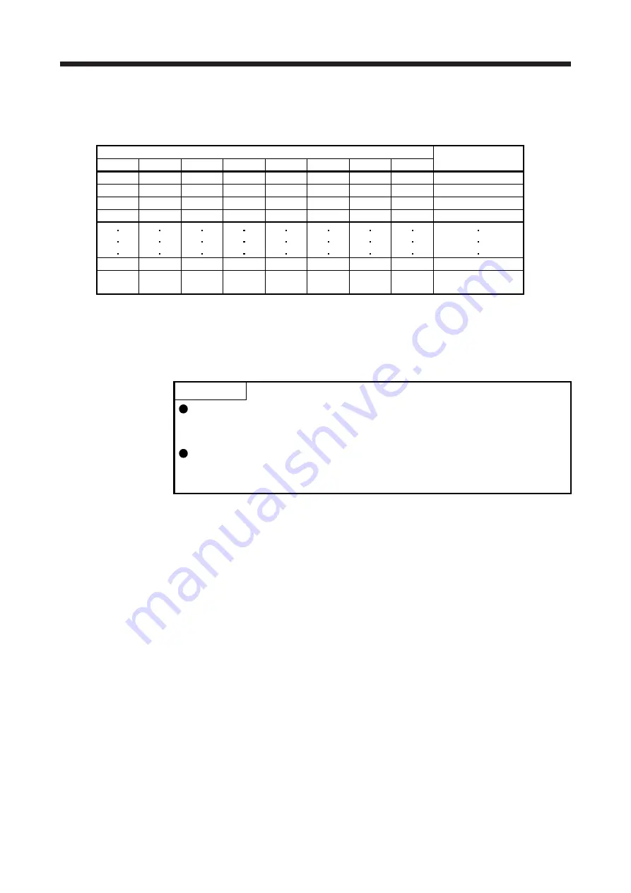
Select a target station No. using 8-bit devices of the DI0 (Next station No. selection 1) to DI7 (Next 
station No. selection 8) for positioning. 


Device (Note 1) 


Selection contents 

DI7 

DI6 

DI5 

DI4 

DI3 

DI2 

DI1 

DI0 

Next station No. 0 

Next station No. 1 

Next station No. 2 

Next station No. 3 


Next station No. 254 

Setting inhibited 

(Note 2) 


Note   1.  0: Off 

1: On 


  2.  [AL. 97.2 Next station position warning] will occur. 


(d)  Timing chart 


POINT 


Be sure to perform a home position return. Executing positioning operation 
without home position return will trigger [AL. 90 Home position return incomplete 
warning] and ST1 (Forward rotation start) will be disabled. 
When a next station position is over the setting value of [Pr. PT28 Number of 
stations per rotation], [AL. 97 Next station position warning] will occur and ST1 
(Forward rotation start) will be disabled. 


Содержание MR-JE-C

Страница 1: ... notice This Instruction Manual uses recycled paper MODEL MODEL CODE General Purpose AC Servo MR JE _C SERVO AMPLIFIER INSTRUCTION MANUAL POSITIONING MODE HEAD OFFICE TOKYO BLDG MARUNOUCHI TOKYO 100 8310 MODEL MR JE _C SERVO AMPLIFIER INSTRUCTION MANUAL POSITIONING MODE Ethernet Interface ...

Страница 2: ... or severe injury CAUTION Indicates that incorrect handling may cause hazardous conditions resulting in medium or slight injury to personnel or may cause physical damage Note that the CAUTION level may lead to a serious consequence according to conditions Please follow the instructions of both levels because they are important to personnel safety What must not be done and what must be done are ind...

Страница 3: ...g them directly or close to combustibles will lead to smoke or a fire Always connect a magnetic contactor between the power supply and the power supply L1 L2 L3 of the servo amplifier in order to configure a circuit that shuts down the power supply on the side of the servo amplifier s power supply If a magnetic contactor is not connected continuous flow of a large current may cause smoke or a fire...

Страница 4: ...anual Do not get on or put heavy load on the equipment Otherwise it may cause injury The equipment must be installed in the specified direction Leave specified clearances between the servo amplifier and the cabinet walls or other equipment Do not install or operate the servo amplifier and servo motor which have been damaged or have any parts missing Do not block the intake and exhaust areas of the...

Страница 5: ... connectors may be disconnected during operation Do not install a power capacitor surge killer or radio noise filter optional FR BIF on the servo amplifier output side To avoid a malfunction connect the wires to the correct phase terminals U V W of the servo amplifier and servo motor Connect the servo amplifier power output U V W to the servo motor power input U V W directly Do not let a magnetic ...

Страница 6: ...due to a collision Do not disassemble repair or modify the product Otherwise an electric shock fire injury etc may occur Disassembled repaired and or modified products are not covered under warranty Before resetting an alarm make sure that the run signal of the servo amplifier is off in order to prevent a sudden restart Otherwise it may cause an accident Use a noise filter etc to minimize the infl...

Страница 7: ...r Electromagnetic brake B RA Contacts must be opened with the emergency stop switch Contacts must be opened when ALM Malfunction or MBR Electromagnetic brake interlock turns off 24 V DC U To prevent an electric shock injury or fire from occurring after an earthquake or other natural disasters ensure safety by checking conditions such as the installation mounting wiring and equipment before switchi...

Страница 8: ...the servo safely Relevant manuals Manual name Manual No MELSERVO MR JE _C Servo Amplifier Instruction Manual SH NA 030257ENG MELSERVO JE Servo Amplifier Instruction Manual Troubleshooting SH NA 030166ENG MELSERVO MR JE _C Servo Amplifier Instruction Manual Network SH NA 030277ENG MELSERVO HG KN HG SN Servo Motor Instruction Manual SH NA 030135ENG MELSERVO EMC Installation Guidelines IB NA 67310ENG...

Страница 9: ... values if necessary according to the following table Quantity SI metric unit U S customary unit Mass 1 kg 2 2046 lb Length 1 mm 0 03937 inch Torque 1 N m 141 6 oz inch Moment of inertia 1 10 4 kg m2 5 4675 oz inch2 Load thrust load axial load 1 N 0 2248 lbf Temperature N C 9 5 32 N F ...

Страница 10: ...parameters 4 13 4 2 1 Basic setting parameters Pr PA_ _ 4 13 4 2 2 Extension setting parameters Pr PC_ _ 4 19 4 2 3 I O setting parameters Pr PD_ _ 4 24 4 2 4 Positioning control parameters Pr PT_ _ 4 32 4 2 5 Network setting parameters Pr PN_ _ 4 44 4 3 Software limit 4 44 4 4 How to set the electronic gear 4 45 4 4 1 Electronic gear settings in the point table method 4 45 4 4 2 Electronic gear s...

Страница 11: ...ble mode pt 7 6 7 2 2 Automatic operation using the point table 7 7 7 3 Related object register 7 11 7 4 Usage 7 15 7 5 Roll feed mode using the roll feed display function 7 35 7 6 Analog override 7 36 7 7 Point table setting method 7 37 7 7 1 Setting procedure 7 37 7 7 2 Detailed setting window 7 39 8 HOW TO USE INDEXER 8 1 to 8 22 8 1 Startup 8 2 8 1 1 Test operation 8 2 8 1 2 Actual operation 8...

Страница 12: ... set type homing 12 29 12 4 6 Torque limit changing data set type 12 30 12 4 7 Stopper type homing 12 32 12 4 8 Home position ignorance servo on position as home position 12 34 12 4 9 Dog type rear end reference home position return 12 35 12 4 10 Count type front end reference home position return 12 37 12 4 11 Dog cradle type homing 12 39 12 4 12 Dog type last Z phase reference home position retu...

Страница 13: ...4 12 6 2 Automatic operation mode 12 76 12 6 3 Manual operation mode 12 83 12 6 4 Backlash compensation and digital override 12 88 12 6 5 Safety precautions 12 91 12 7 Touch probe function setting 12 91 ...

Страница 14: ...contents of MR JE _C Servo Amplifier Instruction Manual For details refer to each section indicated in the detailed explanation field MR JE _C means MR JE _C Servo Amplifier Instruction Manual Item Detailed explanation Combinations of servo amplifiers and servo motors MR JE _C section 1 4 Function list MR JE _C section 1 5 Model designation MR JE _C section 1 6 Structure parts identification MR JE...

Страница 15: ...S pattern acceleration deceleration time constants with Pr PC03 System Signed absolute value command method incremental value command method Indexer Operational specifications Positioning by specifying the station position When using objects registers 255 points when assigning input signals 16 points Note 3 Speed command input Selects the rotation speed and acceleration deceleration time constant ...

Страница 16: ...4 Homing on negative home switch and index pulse Method 5 Homing on negative home switch and index pulse Method 6 Homing on home switch and index pulse Method 7 Homing on home switch and index pulse Method 8 Homing on home switch and index pulse Method 11 Homing on home switch and index pulse Method 12 Homing without index pulse method 19 Homing without index pulse method 20 Homing without index p...

Страница 17: ...on detection backlash compensation overtravel prevention with external limit switch LSP LSN software stroke limit touch probe function override Note 1 STM is the ratio to the setting value of the position data STM can be changed with Pr PT03 Feeding function selection 2 Up to four points of DO are available therefore PT0 Point table No output 1 to PT7 Point table No output 8 cannot be outputted si...

Страница 18: ...rect terminals Otherwise a burst damage etc may occur Ensure that polarity is correct Otherwise a burst damage etc may occur The surge absorbing diode installed to the DC relay for control output should be fitted in the specified direction Otherwise the emergency stop and other protective circuits may not operate DOCOM 24 V DC Servo amplifier RA For sink output interface Control output signal DOCO...

Страница 19: ... Amplifier Instruction Manual For details refer to each section indicated in the detailed explanation field MR JE _C means MR JE _C Servo Amplifier Instruction Manual Item Detailed explanation Input power supply circuit MR JE _C section 3 1 Explanation of power supply system MR JE _C section 3 3 Forced stop deceleration function MR JE _C section 3 7 Alarm occurrence timing chart MR JE _C section 3...

Страница 20: ...nalog torque limit 10 V maximum torque RA1 RA2 24 V DC Note 4 24 V DC Note 4 1 2 3 4 EM2 DOG LSP LSN Reverse rotation stroke end Forced stop 2 Servo on Forward rotation stroke end Note 3 Encoder A phase pulse differential line driver Encoder B phase pulse differential line driver Control common Encoder Z phase pulse differential line driver Malfunction Note 5 Encoder Z phase pulse 10 m or shorter ...

Страница 21: ... MRC2 _ Refer to section 11 4 of MR JE _C Servo Amplifier Instruction Manual 7 Configure a circuit to turn off EM2 when the power is turned off to prevent an unexpected restart of the servo amplifier 8 Refer to section 10 1 for the connection of a manual pulse generator 9 Supply of 24 V DC to CN3 18 pin OPC Power input for open collector sink interface when input devices are assigned to the CN3 6 ...

Страница 22: ...horter 9 2 m or shorter 10 Plate TLA SD LG Analog torque limit 10 V maximum torque RA1 RA2 24 V DC Note 4 24 V DC Note 4 1 2 3 4 EM2 SIG LSP LSN Reverse rotation stroke end Forced stop 2 External limit Rotation direction decision Automatic speed selection Forward rotation stroke end Note 3 Encoder A phase pulse differential line driver Encoder B phase pulse differential line driver Control common ...

Страница 23: ...ally closed contact 6 Use SW1DNC MRC2 _ Refer to section 11 4 of MR JE _C Servo Amplifier Instruction Manual 7 Configure a circuit to turn off EM2 when the power is turned off to prevent an unexpected restart of the servo amplifier 8 The assignments of CN3 14 pin CN3 15 pin CN3 16 pin and CN3 22 pin can be changed with Pr PD29 to Pr PD32 9 For communication function refer to the MR JE _C Servo Amp...

Страница 24: ...2 23 LG LG 24 O LAR LAR 25 O LBR LBR 26 O LZR LZR Note 1 I input signal O output signal 2 CP Positioning mode point table method PS Positioning mode indexer method 3 In the point table method assign the following input device to CN3 2 pin with Pr PD06 CN3 2 DOG Proximity dog 4 In the indexer method assign the following input device to CN3 2 pin with Pr PD06 CN3 2 SIG External limit Rotation direct...

Страница 25: ...ommons to decelerate the servo motor to a stop with commands Turn EM2 on short between commons in the forced stop state to reset that state The following shows the setting of Pr PA04 DI 1 Setting value of Pr PA04 EM2 EM1 Deceleration method EM2 or EM1 is off Alarm occurred 0 _ _ _ EM1 MBR Electromagnetic brake interlock turns off without the forced stop deceleration MBR Electromagnetic brake inter...

Страница 26: ...n Reverse rotation stroke end LSN The stop method can be changed with Pr PD35 Set Pr PD01 as indicated below to switch on the signals keep terminals connected automatically in the servo amplifier Pr PD01 Status LSP LSN _ 4 _ _ Automatic on _ 8 _ _ Automatic on _ C _ _ Automatic on Automatic on When LSP or LSN is turned off AL 99 Stroke limit warning occurs and WNG Warning turns on When using WNG e...

Страница 27: ...on direction specifying indexer You can use this as an input device for specifying a rotation direction of the servo motor The rotation direction varies depending on the setting of Pr PA14 Rotation direction selection Refer to table 2 1 4 Indexer mode idx shortest rotating indexer You can use SIG as an input device for selecting a speed of the servo motor Table 2 1 Rotation direction selection DI ...

Страница 28: ...n with servo on DO 1 Limiting torque TLC TLC turns on when a generated torque reaches a value set with any of Pr PA11 Forward torque limit Pr PA12 Reverse torque limit or TLA Analog torque limit DO 1 Zero speed detection ZSP ZSP turns on when the servo motor speed is zero speed or less Zero speed can be changed with Pr PC17 OFF ON Servo motor speed 20 r min Hysteresis width Pr PC17 20 r min Hyster...

Страница 29: ...data or Pr PT28 Number of stations per rotation was changed DO 1 Home position return completion 2 ZP2 When a home position return completes normally ZP2 Home position return completion 2 turns on ZP2 is always on unless the home position is erased In the incremental system this signal turns off with one of the following conditions 1 AL 69 Command error occurs 2 Home position return is not being e...

Страница 30: ...th MEND Travel completion on DO 1 Point table No output 2 PT1 Device Note 1 2 Description PT7 PT6 PT5 PT4 PT3 PT2 PT1 PT0 Point table No output 3 PT2 0 0 0 0 0 0 0 1 Point table No 1 Point table No output 4 PT3 0 0 0 0 0 0 1 0 Point table No 2 Point table No output 5 PT4 0 0 0 0 0 0 1 1 Point table No 3 Point table No output 6 PT5 Point table No output 7 PT6 1 1 1 1 1 1 1 0 Point table No 254 Poin...

Страница 31: ... 2 Input signal Device Symbol Connector pin No Function and application I O division Control mode CP PS Manual pulse generator PP CN3 6 Connect a manual pulse generator MR HDP01 When using the signal enable PP and NP with Pr PD24 and Pr PD27 DI 2 NP CN3 19 Analog torque limit TLA CN3 9 When using the signal enable TL External torque limit selection with Pr PD06 Pr PD09 Pr PD12 Pr PD15 Pr PD18 Pr P...

Страница 32: ...oint position is reached negative logic The minimum pulse width is about 400 μs For home position return using this pulse set the creep speed to 100 r min or less DO 2 Encoder Z phase pulse open collector OP The encoder zero point signal is outputted in the open collector type When using the signal enable OP with Pr PD38 DO 2 2 4 Power on sequence POINT The output signal etc may be unstable at pow...

Страница 33: ...2 SIGNALS AND WIRING 2 16 MEMO ...

Страница 34: ... use the absolute position detection system first power on results in AL 25 Absolute position erased and the servo on cannot be ready AL 25 can be deactivated by cycling the power Also if the power is switched on when the servo motor is rotated at a speed of 3000 r min or higher a position mismatch may occur due to external force or the like Power must therefore be switched on when the servo motor...

Страница 35: ... parameters according to the structure and specifications of the machine Refer to chapter 4 for details After setting the above parameters turn off the power as necessary Then switch power on again to enable the parameter values 3 Servo on Enable the servo on with the following procedure a Turn on the power b Transmit the servo on command with the controller When the servo on status is enabled the...

Страница 36: ...tor decelerates to a stop Error occurrence Note 1 The servo motor decelerates to a stop Servo amplifier Alarm occurrence The servo motor decelerates to a stop With some alarms however the dynamic brake operates to stop the servo motor Note 2 EM2 Forced stop 2 off The servo motor decelerates to a stop AL E6 Servo forced stop warning occurs In the torque control mode EM2 functions the same as EM1 LS...

Страница 37: ...3 STARTUP 3 4 MEMO ...

Страница 38: ...he referenced item or the instruction manual Character string Reference Section 4 2 1 to 4 2 5 Section 4 2 1 to 4 2 5 of this chapter MR JE _C MR JE _C Servo Amplifier Instruction Manual Network MR JE _C Servo Amplifier Instruction Manual Network Profile MR JE _C Servo Amplifier Instruction Manual Profile Mode 4 1 1 Basic setting parameters Pr PA_ _ POINT In the positioning mode the following para...

Страница 39: ...MR JE _C PB02 VRFT Vibration suppression control tuning mode advanced vibration suppression control II 0000h PB03 PST Position command acceleration deceleration time constant position smoothing 0 ms PB04 FFC Feed forward gain 0 PB05 For manufacturer setting 500 PB06 GD2 Load to motor inertia ratio 7 00 Multiplier PB07 PG1 Model loop gain 15 0 rad s PB08 PG2 Position loop gain 37 0 rad s PB09 VG2 S...

Страница 40: ...5 CNHF Command notch filter 0000h MR JE _C PB46 NH3 Machine resonance suppression filter 3 4500 Hz PB47 NHQ3 Notch shape selection 3 0000h PB48 NH4 Machine resonance suppression filter 4 4500 Hz PB49 NHQ4 Notch shape selection 4 0000h PB50 NH5 Machine resonance suppression filter 5 4500 Hz PB51 NHQ5 Notch shape selection 5 0000h PB52 VRF21 Vibration suppression control 2 Vibration frequency 100 0 ...

Страница 41: ...t 0 ms MR JE _C PC05 SC1 Automatic operation speed 1 100 00 r min Section 4 2 2 PC06 SC2 Automatic operation speed 2 500 00 r min PC07 SC3 Manual operation speed 1 1000 00 r min PC08 SC4 Manual operation speed 2 200 00 r min PC09 SC5 Internal speed command 5 300 00 r min MR JE _C Internal speed limit 5 PC10 SC6 Internal speed command 6 500 00 r min Internal speed limit 6 PC11 SC7 Internal speed co...

Страница 42: ...0 PC54 RSUP1 Vertical axis freefall prevention compensation amount 0 0 0001 rev MR JE _C PC55 For manufacturer setting 0 PC56 100 PC57 0000h PC58 0 PC59 0000h PC60 COPD Function selection C D 0000h MR JE _C PC61 For manufacturer setting 0000h PC62 0000h PC63 0000h PC64 0000h PC65 0000h PC66 LPSPL Touch probe detection range lower four digits 0 10STM μm 10 STM 4 inch pulse Section 4 2 2 PC67 LPSPH ...

Страница 43: ...2h MR JE _C PD06 DI1M Input device selection 1M 0202h Section 4 2 3 PD07 DI1H Input device selection 1H 002Bh Profile PD08 DI2L Input device selection 2L 0A0Ah MR JE _C PD09 DI2M Input device selection 2M 0700h Section 4 2 3 PD10 DI2H Input device selection 2H 000Ah Profile PD11 DI3L Input device selection 3L 0B0Bh MR JE _C PD12 DI3M Input device selection 3M 0800h Section 4 2 3 PD13 DI3H Input de...

Страница 44: ...nction selection D 4 3000h PD39 DOP5 Function selection D 5 0000h PD40 For manufacturer setting 0000h PD41 TPOP Touch probe function selection 0000h Section 4 2 3 PD42 For manufacturer setting 0 PD43 0000h PD44 0000h PD45 0000h PD46 0000h PD47 0000h PD48 0000h 4 1 5 Extension setting 2 parameters Pr PE_ _ No Symbol Name Initial value Unit Detailed explanation PE01 For manufacturer setting 0000h PE...

Страница 45: ...01 PE48 LMOP Lost motion compensation function selection 0000h PE49 LMCD Lost motion compensation timing 0 0 1 ms PE50 LMCT Lost motion compensation non sensitive band 0 pulse kpulse PE51 For manufacturer setting 0000h PE52 0000h PE53 0000h PE54 0000h PE55 0000h PE56 0000h PE57 0000h PE58 0000h PE59 0000h PE60 0000h PE61 0 00 PE62 0 00 PE63 0 00 PE64 0 00 4 1 6 Extension setting 3 parameters Pr PF...

Страница 46: ...000h PF36 0000h PF37 0000h PF38 0000h PF39 0000h PF40 0 PF41 0 PF42 0 PF43 0 PF44 0 PF45 FOP12 Function selection F 12 0000h Network PF46 MIC Modbus RTU communication time out selection 0 s PF47 For manufacturer setting 0000h PF48 0000h 4 1 7 Positioning control parameters Pr PT_ _ POINT In the positioning mode the following parameter cannot be used Pr PT49 Torque slope Pr PT52 Speed limit Pr PT63...

Страница 47: ...h pulse PT22 LNPH 0000h PT23 For manufacturer setting 0 PT24 0 PT25 0 PT26 TOP2 Function selection T 2 0000h Section 4 2 4 PT27 ODM Operation mode selection 0000h PT28 STN Number of stations per rotation 8 stations PT29 TOP3 Function selection T 3 0000h PT30 TPSTL Touch probe sensor Travel distance before stop 0000h 10STM μm 10 STM 4 inch pulse PT31 TPSTH 0000h PT32 For manufacturer setting 0000h ...

Страница 48: ...ch pulse PT60 TOP8 Function selection T 8 0000h PT61 HMA Home position return acceleration time constant 0 ms PT62 HMB Home position return deceleration time constant 0 ms PT63 ZSP2L Zero speed 2 level 50 00 r min Profile PT64 ZSP2F Zero speed 2 filtering time 10 ms PT65 INP2R In position 2 output range 100 10STM μm 10 STM 4 inch pulse Section 4 2 4 PT66 INP2F In position 2 output filtering time 1...

Страница 49: ...eway setting 1 192 PN20 DGW2 Default gateway setting 2 168 PN21 DGW3 Default gateway setting 3 3 PN22 DGW4 Default gateway setting 4 1 PN23 KAA KeepAlive time 3600 s PN24 IPAF1 IP address filter 1 0 PN25 IPAF2 IP address filter 2 0 PN26 IPAF3 IP address filter 3 0 PN27 IPAF4 IP address filter 4 0 PN28 IPFR2 IP address filter 2 range setting 256 PN29 IPFR3 IP address filter 3 range setting 256 PN30...

Страница 50: ...9 Profile mode pp pv tq 0h _ _ x _ For manufacturer setting 0h _ x _ _ 0h x _ _ _ 1h PA06 CMX Electronic gear numerator command pulse multiplication numerator Set an electronic gear numerator To enable the parameter select Electronic gear 0 _ _ _ of Electronic gear selection in Pr PA21 In the positioning mode the setting is effective only after rebooting the power once the parameter values setup i...

Страница 51: ...215 1 PA07 CDV Electronic gear denominator command pulse multiplication denominator Set an electronic gear denominator To enable the parameter select Electronic gear 0 _ _ _ of Electronic gear selection in Pr PA21 In the positioning mode the setting is effective only after rebooting the power once the parameter values setup is completed This parameter corresponds to Shaft revolutions Index 6091h S...

Страница 52: ...ue of the servo motor in the CCW power running or CW regeneration Depending on the setting value of Pr PA14 the polarity of the torque limit changes If set to 0 0 no torque is generated If a value larger than the maximum torque of the servo motor is set the value will be limited to the maximum torque of the servo motor This parameter corresponds to Positive torque limit value Index 60E0h When this...

Страница 53: ... Manual for logic of MELSEC iQ R series MELSEC Q series MELSEC L series MELSEC F series Refer to table 4 1 for setting value 0h _ x _ _ Command input pulse train filter selection Selecting proper filter enables to enhance noise tolerance 0 Command input pulse train is 4 Mpulses s or less 1 Command input pulse train is 1 Mpulses s or less 2 Command input pulse train is 500 kpulses s or less 3 Comma...

Страница 54: ...rd rotation pulse train Reverse rotation pulse train NP PP _ _ 1 1 Signed pulse train PP L H NP _ _ 1 2 A phase pulse train B phase pulse train PP NP _ _ 0 0 Positive logic Forward rotation pulse train Reverse rotation pulse train NP PP _ _ 0 1 Signed pulse train L H PP NP _ _ 0 2 A phase pulse train B phase pulse train PP NP Arrows in the table indicate the timing of importing pulse trains A phas...

Страница 55: ... mode Positioning address decrease Velocity mode Speed command Negative 0 CCW CW 1 CW CCW The following shows the servo motor rotation directions Forward rotation CCW Reverse rotation CW Setting range 0 1 PA21 AOP3 Function selection A 3 _ _ _ x One touch tuning function selection 0 Disabled 1 Enabled When the digit is 0 the one touch tuning is not available 1h _ _ x _ For manufacturer setting 0h ...

Страница 56: ...s parameter corresponds to Profile acceleration Index 6083h When this parameter is mapped to the link device of CC Link IE Field Network Basic do not write the parameter value with MR Configurator2 as the controller overwrites the parameter value written with MR Configurator2 Setting range 0 to 50000 0 ms PC02 STB JOG operation deceleration time constant Set the deceleration time constant during J...

Страница 57: ...omatic operation speed 1 Set the positioning speed for the automatic operation speed mode 1 and 2 Setting range 0 00 to instantaneous permissible speed 100 00 r min PC06 SC2 Automatic operation speed 2 Set the positioning speed for the automatic operation speed mode 1 and 2 Setting range 0 00 to instantaneous permissible speed 500 00 r min PC07 SC3 Manual operation speed 1 Set the JOG operation sp...

Страница 58: ...4 7 for details Setting range 0 to 50000 0 ms PC31 STB2 Deceleration time constant 2 Set the deceleration time constant of position command Setting a value exceeding 20000 ms triggers AL F4 Effective deceleration time constant changes with the combination of parameter input device and Control DI Refer to section 4 7 for details Setting range 0 to 50000 0 ms PC35 TL2 Internal torque limit 2 Set the...

Страница 59: ...mal Refer to Pr PC66 for details The unit can be changed to 10STM μm 10 STM 4 inch or pulse with the setting of Pr PT01 0000h Refer to Function column for unit PC68 LPSNL Touch probe detection range lower four digits Set the lower limit value of the touch probe detection Upper and lower are a set When the roll feed display is enabled set the value with the travel distance from the starting positio...

Страница 60: ... with MR Configurator2 Setting range 00000000h to FFFFFFFFh 0000h Refer to Function column for unit PC76 FEWH Following error output level Upper four digits Set the output level of the following error output Upper and lower are a set Refer to Pr PC75 for details The unit can be changed to 10STM μm 10 STM 4 inch or pulse with the setting of Pr PT01 0000h Refer to Function column for unit PC77 FEWF ...

Страница 61: ... Operation mode selection 2 0 Disabled Use for an external input signal 1 Enabled automatic on _ x _ _ BIN For manufacturer setting x _ _ _ BIN For manufacturer setting _ _ x _ HEX _ _ _ x BIN For manufacturer setting 0h _ _ x _ BIN For manufacturer setting _ x _ _ BIN OVR Analog override selection 0 Disabled Use for an external input signal 1 Enabled automatic on x _ _ _ BIN For manufacturer sett...

Страница 62: ...the setting value into hexadecimal as follows 0 Initial value BIN HEX Input device 0 0 0 0 MD0 Operation mode selection 1 MD1 Operation mode selection 2 0 Initial value BIN HEX Input device 0 0 0 0 OVR Analog override selection 0 BIN 0 Use for an external input signal BIN 1 Automatic on Initial value BIN HEX Input device 0 0 0 0 0 Initial value BIN HEX Input device 0 0 0 0 ...

Страница 63: ...rer setting _ x _ _ HEX _ _ _ x BIN DI0 Point table No Next station No selection 1 0 Disabled Use for an external input signal 1 Enabled automatic on 0h _ _ x _ BIN DI1 Point table No next station No selection 2 0 Disabled Use for an external input signal 1 Enabled automatic on _ x _ _ BIN DI2 Point table No next station No selection 3 0 Disabled Use for an external input signal 1 Enabled automati...

Страница 64: ... Initial value BIN HEX Input device 0 0 0 0 DI4 Point table No Next station No selection 5 DI5 Point table No Next station No selection 6 DI6 Point table No Next station No selection 7 DI7 Point table No Next station No selection 8 0 BIN 0 Use for an external input signal BIN 1 Automatic on Initial value BIN HEX Input device 0 0 0 0 DI2 Point table No next station No selection 3 DI3 Point table No...

Страница 65: ... _ 2 4 TP0 _ _ 2 5 TP1 _ _ 2 6 OVR _ _ 2 7 TSTP _ _ 2 B DOG SIG _ _ 3 1 RT _ _ 3 2 RTCDP _ _ 3 4 OV0 _ _ 3 5 OV1 _ _ 3 6 OV2 _ _ 3 7 OV3 _ _ 3 8 DI0 DI0 _ _ 3 9 DI1 DI1 _ _ 3 A DI2 DI2 _ _ 3 B DI3 DI3 _ _ 3 C DI4 DI4 _ _ 3 D DI5 DI5 _ _ 3 E DI6 DI6 _ _ 3 F DI7 DI7 Note The diagonal lines indicate manufacturer settings Never change the setting PD09 DI2M Input device selection 2M Optional input devi...

Страница 66: ...sitioning mode Device selection Refer to table 4 2 in Pr PD06 for setting value 20h PD24 DI7M Input device selection 7M Optional input device can be assigned to the CN3 6 pin _ _ x x Not used with the positioning mode 00h x x _ _ Positioning mode Device selection Refer to table 4 2 in Pr PD06 for setting value When 00 is set PP Forward rotation pulse Manual pulse generator is assigned 00h PD27 DI8...

Страница 67: ... A SA Always off _ _ 0 B Always off Always off _ _ 0 C ZSP ZSP _ _ 0 D MTTR MTTR _ _ 0 F CDPS CDPS _ _ 1 1 ABSV ABSV _ _ 1 7 ZP2 ZP2 _ _ 2 3 CPO CPO _ _ 2 4 ZP ZP _ _ 2 5 POT _ _ 2 6 PUS _ _ 2 7 MEND MEND _ _ 2 C PED _ _ 3 1 ALMWNG ALMWNG _ _ 3 2 BW9F BW9F _ _ 3 3 TPR1H _ _ 3 4 TPR1L _ _ 3 8 PT0 PS0 _ _ 3 9 PT1 PS1 _ _ 3 A PT2 PS2 _ _ 3 B PT3 PS3 _ _ 3 C PT4 PS4 _ _ 3 D PT5 PS5 _ _ 3 E PT6 PS6 _ _...

Страница 68: ... x _ _ For manufacturer setting 0h x _ _ _ 0h PD35 DOP1 Function selection D 1 _ _ _ x Stop method selection for when either the LSP Forward rotation stroke end or the LSN Reverse rotation stroke end is off Select a stop method for when the either LSP Forward rotation stroke end or the LSN Reverse rotation stroke end is off Refer to section 4 5 1h Setting value Control mode CP PS 0 Quick stop 1 Sl...

Страница 69: ...ic do not write the parameter value with MR Configurator2 as the controller overwrites the parameter value written with MR Configurator2 0h _ _ x _ Manual pulse generator multiplication 0 1 1 10 2 100 0h _ x _ _ Not used with the positioning mode 0h x _ _ _ For manufacturer setting 0h PT05 ZRF Home position return speed Set the servo motor speed for the home position return This parameter correspo...

Страница 70: ...T01 Feed length multiplication STM in Pr PT03 Pr PT45 Setting range 0 to 65535 0 Refer to Function column for unit PT09 DCT Travel distance after proximity dog Set the travel distance after proximity dog for the count type front end detection Z phase reference Homing method 2 34 and home position return for dog reference A maximum of 231 can be set with Pr PT59 The following shows the home positio...

Страница 71: ...es in the opposite direction Setting range 0 to 65535 0 pulse PT15 LMPL Software limit Lower four digits Set an address increasing side of the software stroke limit Upper and lower are a set Set an address in hexadecimal Setting address Upper four digits Lower four digits Pr PT15 Pr PT16 The stop method follows the Stopping method at software limit detection of Pr PD35 The initial value is slow st...

Страница 72: ...h the setting of Pr PT01 This parameter corresponds to Min position limit Index 607Dh Sub 1 When this parameter is mapped to the link device of CC Link IE Field Network Basic do not write the parameter value with MR Configurator2 as the controller overwrites the parameter value written with MR Configurator2 Setting range 00000000h to FFFFFFFFh 0000h Refer to Function column for unit PT18 LMNH Soft...

Страница 73: ...rent position and for the command position 0h Setting value Displayed data Operation mode Status display contents Current position Command position _ _ 0 _ Positioning display Auto Manual Display the actual current position with the machine home position set to 0 Display the command current position with the machine home position set to 0 _ _ 1 _ Roll feed display Automatic Display the actual curr...

Страница 74: ...x _ For manufacturer setting 0h _ x _ _ 0h x _ _ _ 0h Convert the setting value into hexadecimal as follows 0 Initial value BIN HEX Setting 0 0 0 0 0 0 0 Proximity dog input polarity or External limit Rotation direction input polarity Touch probe 1 input polarity PT30 TPSTL Touch probe sensor Travel distance before stop lower four digits Set Touch probe sensor Travel distance before stop Upper and...

Страница 75: ...klash compensation assuming a command was issued to the CCW rotation direction before the home position return When setting this digit execute a home position return again 0h PT39 INT Torque limit delay time Set the delay time from output In position S_INP INP to enabling Pr PC 35 internal torque limit 2 or Torque limit value 2 Index 2D2Bh Setting range 0 to 1000 100 ms PT40 SZS Station home posit...

Страница 76: ... Fixed to 100 0 0 0 1 Pr PT42 0 0 1 0 Pr PT42 Pr PT43 1 0 0 1 1 Pr PT42 Pr PT43 2 0 1 0 0 Pr PT42 Pr PT43 3 0 1 0 1 Pr PT42 Pr PT43 4 0 1 1 0 Pr PT42 Pr PT43 5 0 1 1 1 Pr PT42 Pr PT43 6 1 0 0 0 Pr PT42 Pr PT43 7 1 0 0 1 Pr PT42 Pr PT43 8 1 0 1 0 Pr PT42 Pr PT43 9 1 0 1 1 Pr PT42 Pr PT43 10 1 1 0 0 Pr PT42 Pr PT43 11 1 1 0 1 Pr PT42 Pr PT43 12 1 1 1 0 Pr PT42 Pr PT43 13 1 1 1 1 Fixed to 0 Note 0 Of...

Страница 77: ...eter value with MR Configurator2 as the controller overwrites the parameter value written with MR Configurator2 37 Setting value Home position return direction Home position return method Setting value Home position return direction Home position return method 1 Address increasing direction Dog type rear end detection Z phase reference torque limit changing dog type Note 33 Address decreasing dire...

Страница 78: ...thod 37 Note Torque limit changing dog type and torque limit changing data set type are available only in the indexer method PT50 PVC Profile speed command Set the speed of the profile speed command The fractional portion of the parameter will be rounded down When Pr PN08 is set to _ _ _ 1 this function is effective in the JOG operation mode and in the indexer mode This parameter corresponds to Pr...

Страница 79: ...s Home position return position data Pr PT08 Pr PT58 x 65536 The unit is changed to 10STM μm 10 STM 4 inch or pulse with the setting of Pr PT01 Additionally when the following parameters are changed the home position return position data is changed Execute the home position return again Position data unit in Pr PT01 Feed length multiplication STM in Pr PT03 Home position return type in Pr PT45 Set...

Страница 80: ...e parameter setting value continues for the time set in Pr PT66 In position 2 output filtering time or longer Statusword Index 6041h bit 10 Target reached is turned on However when this parameter is set to 65535 Statusword Index 6041h bit 10 Target reached is always on This function is effective only in the point table mode and in the JOG operation mode The unit is changed to µm 10 4 inch or pulse...

Страница 81: ...5 communication Modbus RTU Communications other than selected communication function are unavailable 0h 4 3 Software limit The limit stop with the software limit Pr PT15 to Pr PT18 is the same as the motion of the stroke end Exceeding a setting range will stop and servo lock the shaft This will be enabled at power on and will be disabled at home position return Setting a same value to Software lim...

Страница 82: ...ng setting example shows how to calculate the electronic gear POINT To calculate the electronic gear the following specifications are required Pb Ball screw lead mm 1 n Reduction ratio Pt Servo motor encoder resolution pulse rev ΔS Travel distance per servo motor revolution mm rev 1 Setting example of a ball screw Machine specifications Ball screw lead Pb 10 mm Reduction ratio 1 n Z1 Z2 1 2 Z1 Num...

Страница 83: ...whole number Therefore set CMX 16384 and CDV 20944 4 4 2 Electronic gear setting in the indexer method Using Pr PA06 and Pr PA07 adjust the rotation amount m of the servo motor shaft which is required to rotate the load side for n times The following shows a setting example of the electronic gear 1 Number of pulley teeth on machine side 50 number of pulley teeth on servo motor side 20 Set Pr PA06 ...

Страница 84: ... Without S pattern acceleration deceleration Travels for the droop pulses portion and stops the servo motor Erases the home position A difference will be generated between the command position and the current position Perform a home position return again _ _ _ 2 Servo motor speed 0 r min ON OFF Decelerates to stop Acceleration deceleration time constant Acceleration deceleration time constant S pa...

Страница 85: ...ern acceleration deceleration Without S pattern acceleration deceleration Travels for the droop pulses portion and stops the servo motor Erases the home position A difference will be generated between the command position and the current position Perform a home position return again _ 2 _ _ Servo motor speed 0 r min Software limit detection Acceleration deceleration time constant S pattern acceler...

Страница 86: ...084h On Pr PC30 Pr PC31 _ _ _ 1 Off The values of any of Pr PC01 6083h Pr PC02 6084h Pr PT50 6081h is 0 2801h to 28FFh All the values of Pr PC01 6083h Pr PC02 6084h Pr PT50 6081h are other than 0 Pr PC01 6083h Pr PC02 6084h On The values of any of Pr PC30 Pr PC31 Pr PT50 6081h is 0 2801h to 28FFh All the values of Pr PC30 Pr PC31 Pr PT50 6081h are other than 0 Pr PC30 Pr PC31 2 Home position retur...

Страница 87: ...to be used for the positioning operation from the general purpose interface and from the communication interface When performing the positioning operation with the communication interface the input devices available via DI are limited to the list on the following table Device Symbol Forward rotation stroke end LSP Reverse rotation stroke end LSN Proximity dog DOG External limit Rotation direction ...

Страница 88: ... the master station controller changes the status of the slave stations servo amplifiers The current servo amplifier status can be read with the control status 6041h Power on 14 13 Ready off Servo off Main circuit charging completed Ready off Servo off During main circuit charging Ready on Servo on 9 8 12 11 16 H Fault Error occurs Transition by slave Transition by master Transition by slave or ma...

Страница 89: ... transitions with the Disable Voltage command from the master Operation is disabled after servo off or RA off 10 The state transitions with the Disable Voltage command or Quick Stop command from the master RA turns off 11 The state transitions with the Quick Stop command from the master Quick Stop starts 12 a The state automatically transitions after Quick Stop is completed If the Quick Stop optio...

Страница 90: ... Halt 0 Operation ready 1 Temporary stop 9 Operation Mode Specific Differs depending on Modes of operation 6060h Refer to chapter 6 to chapter 9 10 to 14 Reserved The value at reading is undefined Set 0 when writing 15 New set point 0 The servo motor is stopped 1 The servo motor is driven Note 1 The description changes depending on the control mode 2 The value at reading is undefined Set 0 when wr...

Страница 91: ...s of operation 6060h Refer to chapter 6 to chapter 9 11 ILA Internal limit active 0 The forward rotation stroke end reverse rotation stroke end and software position limit have not been reached 1 The forward rotation stroke end reverse rotation stroke end or software position limit has been reached Enabled in the pp pv or hm mode 12 to 13 OMS Operation Mode Specific Differs depending on Modes of o...

Страница 92: ...disabled Enable operation E Operation enabled C Ready to switch on Enable operation E Operation enabled 5 2 Control mode This section describes the control modes of the MR JE _C servo amplifier 5 2 1 Function description A control mode of the MR JE _C servo amplifier can be selected with the control mode Modes of operation 6060h Control mode after switching Position Speed Torque Profile Positionin...

Страница 93: ...s Index Sub Index Access Name Data type Default 6060h 0 rw Modes of operation I8 0 6061h 0 ro Modes of operation Display I8 20 6502h 0 ro Supported Drive Modes U32 Note Note For the Default value refer to the MR JE _C Servo Amplifier Instruction Manual Network ...

Страница 94: ...usword 6041h Controlword 6040h Homing acceleration 609Ah Homing method 6098h Homing speeds 6099h Home offset 607Ch Homing method Statusword 6041h 1 Parameters for home position return To perform the home position return set each parameter as follows Select the polarity where the proximity dog is detected with DOG Proximity dog polarity selection of Pr PT29 Function selection T 3 Setting 0 detects ...

Страница 95: ...urning on Controlword bit4 Homing operation start after the temporary stop is reset restarts the home position return Controlword bit4 Homing operation start does not function even it is switched on during a temporary stop The temporary stop restart input functions in the following status Operation status Point table Jog operation Home position return During a stop Temporary stop Temporary stop Du...

Страница 96: ...nit 0 01 r min Range 0 to servo motor maximum speed 2 rw Speed during search for zero U32 1000 Specify the travel speed to the home position after dog detection Note Unit Vel unit 0 01 r min Range 0 to servo motor maximum speed 609Ah 0 rw Homing acceleration U32 0 Acceleration deceleration time constant at home position return Unit ms 60E3h 0 ro Supported Homing Method U8 40 Number of entries of t...

Страница 97: ...0 when writing 10 to 14 Refer to section 5 1 2 15 Reserved The value at reading is undefined Set 0 when writing To start a home position return operation turn bit 4 from 0 to 1 When the home position return operation is completed or an alarm is issued during the return operation turn bit 4 from 1 to 0 When bit 8 Halt of Controlword 6040h is set to 1 the servo motor decelerates to a stop After that...

Страница 98: ...on return The direction of rotation is opposite to that of the method 8 19 Homing without index pulse Forward rotation Same as the dog type front end reference home position return Note that if the stroke end is detected during home position return AL 90 Home position return incomplete warning occurs 20 Homing without index pulse Forward rotation Although this type is the same as the dog cradle ty...

Страница 99: ...ft distance The position after the shifts is set as the home position 33 Homing on index pulse Reverse rotation Although this type is the same as the dogless Z phase reference home position return the creep speed is applied as the movement start speed 34 Homing on index pulse Forward rotation Although this type is the same as the dogless Z phase reference home position return the creep speed is ap...

Страница 100: ...e the servo is switched on is used as the home position 6 Dog type Rear end detection rear end reference Forward rotation Deceleration starts from the front end of the proximity dog After the rear end is passed the position is shifted by the travel distance after proximity dog and the home position shift distance The position after the shifts is set as the home position If the stroke end is detect...

Страница 101: ...ully unless 0 is set in Bit 12 The following shows the conditions when 0 is set in Bit 12 For incremental system At power on At communication shut off by master station controller reset At home position return start At home position erasure For absolute position detection system At home position return start At home position erasure To check the home position return status with Statusword 6041h no...

Страница 102: ...ommand is input again bit 10 turns off 0 b Bit 12 Homing attained of Statusword 6041h Bit 12 turns off 0 when a home position return operation is started and turns on 1 when the operation is completed For absolute position detection system bit 12 turns on 1 after the power supply is turned on c Bit 13 Homing error of Statusword 6041h Bit 13 turns on 1 when an alarm or warning AL 90 2 AL 90 3 AL 90...

Страница 103: ... completion Set 0Fh in Controlword 6040h Operation enable Check that bit 12 Homing attained of Statusword 6041h is 1 Check that the control mode has been switched to Homing mode hm with Modes of operation Display 6061h Save the object in the EEP ROM by using Save all parameters in Store parameters 1010h Set 1Fh in Controlword 6040h to start home position return Save the object in the EEP ROM by us...

Страница 104: ...e last Z phase reference home position return and Method 4 has the operation of the dog cradle type home position return at a forward rotation start However if the stroke end is detected during home position return AL 90 occurs 3 3 4 4 Index Pulse Home Switch 2 Method 5 and 6 Homing on negative home switch and index pulse These home position return types use the front end of the proximity dog as r...

Страница 105: ... reverse in Method 11 and 12 7 7 7 8 8 8 Index Pulse Home Switch Positive Limit Switch 4 Method 17 to 30 Homing without index pulse Method 17 to 30 have the operation of Method 1 to Method 14 however these types set the home position on the dog but not on the Z phase The following figure shows the operation of the home position return type of Method 19 and Method 20 Method 19 and Method 20 have th...

Страница 106: ...at the start Index Pulse 33 34 6 Method 35 and 37 Homing on current position These home position return types set the current position as a home position The operation is the same as that of the data set type home position return however these types can be executed even during servo off ON OFF ON OFF Statusword bit 12 Homing attained Controlword bit 4 Homing operation start Home position return po...

Страница 107: ...tatusword bit 12 Homing attained ON OFF ON OFF Controlword bit 4 Homing operation start Home position return speed Deceleration time constant Home position shift distance Home position return position data ON OFF Proximity dog Creep speed Z phase DOG Proximity dog Acceleration time constant Home position return direction Home position return start position After retracting to before proximity dog ...

Страница 108: ...Forward rotation Statusword bit 10 Target reached ON OFF ON OFF Statusword bit 12 Homing attained ON OFF ON OFF Controlword bit 4 Homing operation start ON OFF Z phase DOG Proximity dog Acceleration time constant Servo motor speed Reverse rotation 0 r min Forward rotation Home position return direction Home position return start position Home position shift distance Home position return position d...

Страница 109: ... Home position return position data ON OFF Proximity dog Creep speed Z phase DOG Proximity dog Acceleration time constant 10 ms or shorter Servo motor speed Reverse rotation 0 r min Home position return direction Home position return start position After retracting to before proximity dog the home position return starts from here Proximity dog When a home position return is started from the proxim...

Страница 110: ...OFF ON OFF Controlword bit 4 Homing operation start ON OFF Z phase DOG Proximity dog Acceleration time constant 10 ms or shorter Servo motor speed Reverse rotation 0 r min Forward rotation Home position return direction Home position return start position Home position shift distance Home position return position data Proximity dog When a home position return is started from the proximity dog Serv...

Страница 111: ...tation Statusword bit 10 Target reached ON OFF Statusword bit 12 Homing attained ON OFF Controlword bit 4 Homing operation start DOG Proximity dog Acceleration time constant 10 ms or shorter Servo motor speed Reverse rotation 0 r min Home position return direction Home position return start position After retracting to before proximity dog the home position return starts from here Proximity dog Wh...

Страница 112: ...d ON OFF ON OFF Statusword bit 12 Homing attained ON OFF ON OFF Controlword bit 4 Homing operation start ON OFF Z phase DOG Proximity dog Acceleration time constant 10 ms or shorter Servo motor speed Reverse rotation 0 r min Forward rotation Home position return direction Home position return start position Home position shift distance Travel distance after proximity dog Home position return posit...

Страница 113: ...F Statusword bit 12 Homing attained ON OFF Controlword bit 4 Homing operation start DOG Proximity dog Acceleration time constant 10 ms or shorter Servo motor speed Reverse rotation 0 r min Home position return direction Home position return start position After retracting to before proximity dog the home position return starts from here Proximity dog When a home position return is started from the...

Страница 114: ...ON OFF Controlword bit 4 Homing operation start ON OFF Z phase DOG Proximity dog Acceleration time constant 10 ms or shorter Servo motor speed Reverse rotation 0 r min Forward rotation Home position return direction Home position return start position Home position shift distance Travel distance after proximity dog Home position return position data Proximity dog When a home position return is sta...

Страница 115: ... OFF Statusword bit 12 Homing attained ON OFF Z phase Acceleration time constant 10 ms or shorter Servo motor speed 0 r min Forward rotation Home position return start position Home position return direction The servo motor stops due to the occurrence of AL 90 Stroke end When the stroke end is detected 10 Method 35 and Method 37 Homing on current position The following figure shows the operation o...

Страница 116: ...phase DOG Proximity dog Acceleration time constant 10 ms or shorter Note After the front end of the proximity dog is detected if the distance after proximity dog is traveled without reaching the creep speed AL 90 occurs Set the travel distance after proximity dog enough for the servo motor to decelerate from the home position return speed to the creep speed Servo motor speed Reverse rotation 0 r m...

Страница 117: ...linear servo motor travel distance per stop interval selection at the home position return of Pr PL01 2 Adjustment For the dog type home position return adjust the setting so that the Z phase signal is always generated during the detection of a dog Make an adjustment so that the rear end of DOG Proximity dog is positioned almost at the center between the positions specified by a Z phase signal and...

Страница 118: ...sword bit 12 Homing attained ON OFF Power supply ON OFF ON OFF DOG Proximity dog ON OFF Controlword bit 4 Homing operation start Point actual value Set time in Pr PT61 Note Positive torque limit value Negative torque limit value Torque limit value2 Torque limit value2 Creep speed Home position return speed Z phase Enabled torque limit value Position where the station home position shift distance i...

Страница 119: ...mity dog Note Deceleration time constant Home position return position data Servo motor speed Reverse rotation 0 r min Forward rotation Statusword bit 10 Target reached ON OFF ON OFF Statusword bit 12 Homing attained ON OFF ON OFF Controlword bit 4 Homing operation start ON OFF Z phase DOG Proximity dog Acceleration time constant Travel distance after proximity dog Home position shift distance 10 ...

Страница 120: ...Statusword bit 12 Homing attained Controlword bit 4 Homing operation start Home position return position data Servo motor speed Reverse rotation 0 r min Forward rotation b Torque limit changing data set type home position return The following figure shows the operation of Homing method 3 in the indexer mode This type cannot be executed during servo off Reverse rotation Forward rotation Servo motor...

Страница 121: ...t reached ON OFF Acceleration time constant 5 ms or longer ON OFF TLC Limiting torque Torque limit value Torque limit value Note 1 Pr PT11 Torque limit value Note 1 Note 2 Stopper Pr PT10 Stopper type home position return stopper time 0 r min 10 ms or shorter Note 1 When Method 4 is set the torque limit value of Positive torque limit value 60E0h is applied When Method 36 is set the torque limit va...

Страница 122: ...urn speed Creep speed Proximity dog Note Deceleration time constant Home position return position data Servo motor speed Reverse rotation 0 r min Forward rotation Statusword bit 10 Target reached ON OFF ON OFF Statusword bit 12 Homing attained ON OFF ON OFF Controlword bit 4 Homing operation start DOG Proximity dog Acceleration time constant 10 ms or shorter Note After the front end of the proximi...

Страница 123: ... min Forward rotation The home position return starts from here Home position return direction Home position return start position Proximity dog Stroke end Note Note This is not available with the software limit When the servo motor returns at the stroke end ...

Страница 124: ...eturn position data Servo motor speed Reverse rotation 0 r min Forward rotation Statusword bit 10 Target reached ON OFF ON OFF Statusword bit 12 Homing attained ON OFF ON OFF Controlword bit 4 Homing operation start DOG Proximity dog Acceleration time constant Travel distance after proximity dog Home position shift distance 10 ms or shorter Servo motor speed Reverse rotation 0 r min Home position ...

Страница 125: ... attained ON OFF ON OFF Controlword bit 4 Homing operation start ON OFF Z phase DOG Proximity dog Acceleration time constant Servo motor speed Reverse rotation 0 r min Forward rotation Home position return direction Home position return start position Home position shift distance Home position return position data Proximity dog When a home position return is started from the proximity dog Servo mo...

Страница 126: ...oximity dog 10 ms or shorter Note After the front end of the proximity dog is detected if the rear end of the proximity dog is detected without stop AL 90 occurs Revise the length of the proximity dog or revise both the home position return speed and creep speed Servo motor speed Reverse rotation 0 r min Home position return direction Home position return start position After retracting to before ...

Страница 127: ...me constant 10 ms or shorter Note After the front end of the proximity dog is detected if the rear end of the proximity dog is detected without reaching the creep speed AL 90 occurs Revise the length of the proximity dog or revise both the home position return speed and creep speed Servo motor speed Reverse rotation 0 r min Home position return direction Home position return start position After r...

Страница 128: ...tor speed Reverse rotation 0 r min Forward rotation Statusword bit 10 Target reached ON OFF Statusword bit 12 Homing attained ON OFF Z phase Acceleration time constant Deceleration time constant Home position shift distance Home position return speed Home position return position data 10 ms or shorter Servo motor speed 0 r min Forward rotation Home position return start position Home position retu...

Страница 129: ...6 HOMING MODE 6 36 MEMO ...

Страница 130: ... servo motor is operated at a servo motor speed higher than the limit value AL E3 Absolute position counter warning occurs 7 1 Startup WARNING When executing a test run follow the notice and procedures in this instruction manual Otherwise it may cause a malfunction damage to the machine or injury Do not operate switches with wet hands Otherwise it may cause an electric shock CAUTION Before startin...

Страница 131: ...s RD Ready switches on 2 Switch on LSP Forward rotation stroke end and LSN Reverse rotation stroke end 3 When 100 is set in Modes of operation 6060h by the controller and bit 4 of Controlword 6040h is turned on in the Jog mode jg the servo motor rotates Set a low speed in Profile velocity 6081h at first and then operate the servo motor in order to check the rotation direction of the servo motor et...

Страница 132: ...de are outputted in 4 bit binary respectively Refer to section 7 2 2 for details of the point table 7 1 3 Single step feed CAUTION The test operation mode is designed for checking servo operation Do not use it for an actual operation If the servo motor operates unexpectedly use EM2 Forced stop 2 to stop it POINT MR Configurator2 is required to perform single step feed Test operation cannot be perf...

Страница 133: ...ation Start actual operation after confirmation of normal operation by test operation and completion of the corresponding parameter settings 7 1 5 Troubleshooting at start up CAUTION Never make a drastic adjustment or change to the parameter values as doing so will make the operation unstable POINT Using MR Configurator2 you can refer to the reason for rotation failure etc The following faults may...

Страница 134: ...ion return is not completed Check the on off status of DOG Proximity dog The proximity dog is set incorrectly 4 Switch on Controlword bit 4 New set point Servo motor does not rotate Check the status of LSP Forward rotation stroke end and LSN Reverse rotation stroke end LSP and LSN are off Check Pr PA11 Forward rotation torque limit and Pr PA12 Reverse rotation torque limit Torque limit level is to...

Страница 135: ...ddress to be reached Setting range 999999 to 999999 10STM μm STM Feed length multiplication Pr PT03 999999 to 999999 10 STM 4 inch STM Feed length multiplication Pr PT03 999999 to 999999 pulse Setting range of the position data 10STM μm 10 STM 4 inch pulse 999999 999999 2 Incremental value command method As position data set the travel distance from the current address to the target address Settin...

Страница 136: ... motor speed the servo motor may not rotate Acceleration time constant 0 to 20000 ms Set a time for the servo motor to reach the rated speed Deceleration time constant 0 to 20000 ms Set a time for the servo motor to stop from the rated speed Dwell 0 to 20000 ms Set the dwell To disable the dwell set 0 or 2 to the auxiliary function Setting 1 3 8 9 10 or 11 in the auxiliary function and 0 in the dw...

Страница 137: ...01 Set the unit of the position data Pr PT01 setting Position data unit _ 0 _ _ mm _ 1 _ _ inch _ 3 _ _ pulse 4 Feed length multiplication Pr PT03 Set the feed length multiplication factor STM of the position data Pr PT03 setting Position data input range Note 1 mm inch pulse Note 2 _ _ _ 0 999 999 to 999 999 99 9999 to 99 9999 _ _ _ 1 9999 99 to 9999 99 999 999 to 999 999 999999 to 999999 _ _ _ 2...

Страница 138: ...ch pulse Set the travel distance The unit can be changed by Pr PT03 Feed length multiplication Servo motor speed 0 to permissible speed 0 01 r min Set the command speed of the servo motor for execution of positioning The setting value must be equal to or less than the instantaneous permissible speed of the servo motor used Acceleration time constant 0 to 20000 ms Set a time for the servo motor to ...

Страница 139: ... rotation address decrease 1 CW rotation address increase CCW rotation address decrease Pr PA14 0 Pr PA14 1 CW CW Controlword bit 5 off Controlword bit 5 off Controlword bit 5 on Controlword bit 5 on CCW CCW 3 Position data unit Pr PT01 Set the unit of the position data Pr PT01 setting Position data unit _ 0 _ _ mm _ 1 _ _ inch _ 3 _ _ pulse 4 Feed length multiplication Pr PT03 Set the feed length...

Страница 140: ...rolword Switch on Controlword bit 4 New set point 7 3 Related object register The following shows the functions and the related objects registers of the point table mode pt Position trajectry generator Control effort 60FAh Position actual internal value 6063h Acceleration limit function Position limit function Position control Velocity control Torque control Encoder Motor Torque limit value 60E0h ...

Страница 141: ... pulse 2147483647 607Dh 0 Software position limit U8 ro 2 Number of entries 1 Min position limit I32 rw 0 Minimum position address Pos units 2 Max position limit I32 rw 0 Maximum position address Pos units 607Eh Polarity U8 rw 00h Polarity selection Bit 7 Position POL Bit 6 Velocity POL Bit 5 Torque POL 6085h Quick stop deceleration U32 rw 100 Deceleration time constant for Quick stop Unit ms 6091...

Страница 142: ...tly specified point table No is returned While the servo motor is stopped the value becomes the set value of the Target point table 2D60h 2D69h Point actual value I16 ro Current point table The completed point table is returned 2D6Ah M code actual value U8 ro Current M code The completed M code of the point table is returned 2 Details of the OMS Bit of Controlword pt mode Bit Symbol Description 4 ...

Страница 143: ...1 the difference between the current position and the point table command position is equal to or less than the value set in Position window 6067h and 2 the time of status 1 is longer than the time set in Position window time 6068h 12 Set point acknowledge 0 Positioning completed waiting for next command 1 Positioning being executed 13 Following error 0 No following error 1 Following error Judgmen...

Страница 144: ...rget point table Forward rotation 0 r min Reverse rotation Servo motor speed ON OFF INP S_INP In position ON OFF Status DO 5 bit 5 S_CPO Rough match ON OFF Status DO 5 bit 6 S_MEND Travel completion ON OFF Statusword bit 10 Target reached ON OFF Point actual value M code actual value Point demand value Point table No 1 Point table No 2 1 2 1 1 2 Controlword bit 5 Direction Note 1 ON OFF 2 M code o...

Страница 145: ... OFF Controlword bit 4 New set point Target point table ON OFF ON OFF ON OFF Statusword bit 10 Target reached ON OFF ON OFF Point actual value M code actual value Point demand value 1 2 1 1 2 2 Note ON OFF Controlword bit 5 Direction Forward rotation 0 r min Reverse rotation Servo motor speed INP S_INP In position Status DO 5 bit 5 S_CPO Rough match Status DO 5 bit 6 S_MEND Travel completion Point...

Страница 146: ...lue command method and point table No 2 to the incremental value command method Point table No Position data 10STM μm Servo motor speed r min Acceleration time constant ms Deceleration time constant ms Dwell ms Auxiliary function M code 1 5 00 3000 00 100 150 100 1 5 2 5 00 2000 00 150 200 200 3 10 3 15 00 1000 00 300 100 Disabled 0 Note 15 Note Be sure to set 0 or 2 to the auxiliary function of t...

Страница 147: ...8 00 1000 00 300 100 Disabled 0 Note 15 Note Be sure to set 0 or 2 to the auxiliary function of the last point table of the consecutive point tables 0 When using the point table with the absolute value command method 2 When using the point table with the incremental value command method Speed 3000 00 Speed 2000 00 Position address Target point table Controlword bit 4 New set point ON OFF Point act...

Страница 148: ...n M code 1 5 00 3000 00 100 150 100 1 5 2 6 00 2000 00 150 200 200 1 10 3 3 00 1000 00 300 100 Disabled 0 Note 15 Note Be sure to set 0 to the auxiliary function of the last point table of the consecutive point tables Target point table Controlword bit 4 New set point ON OFF Controlword bit 5 Direction Note ON OFF Point actual value 6 00 0 5 00 11 00 14 00 1 1 M code actual value 05 3 00 Servo mot...

Страница 149: ...nt tables is disabled By setting 1 or 3 to auxiliary functions until point table No 254 the operation can be performed at maximum 255 speeds Be sure to set 0 or 2 to the auxiliary function of the last point table To perform varying speed operation be sure to set 0 to the dwell Setting 1 or more enables the automatic continuous positioning operation The following table shows an example of setting P...

Страница 150: ... Disabled 0 3 10 3 10 00 1000 00 Disabled Disabled 0 1 15 4 6 00 500 00 Disabled Disabled 0 2 Note 2 20 Note 1 Be sure to set 0 2 Be sure to set 0 or 2 to the auxiliary function of the last point table of the consecutive point tables 0 When using the point table with the absolute value command method 2 When using the point table with the incremental value command method Deceleration time constant ...

Страница 151: ...sabled 0 3 10 3 8 00 1000 00 Disabled Disabled Disabled 0 Note 2 15 Note 1 Be sure to set 0 2 Be sure to set 0 or 2 to the auxiliary function of the last point table of the consecutive point tables 0 When using the point table with the absolute value command method 2 When using the point table with the incremental value command method Target point table Controlword bit 4 New set point ON OFF Point...

Страница 152: ...table data 5 0 1 6 Disabled 0 Note 2 Note 1 Be sure to set 0 2 Be sure to set 0 to the auxiliary function of the last point table of the consecutive point tables The following shows an operation example with the set values listed in the table below Point table No Position data 10STM μm Servo motor speed r min Acceleration time constant ms Deceleration time constant ms Dwell ms Note 1 Auxiliary fun...

Страница 153: ...hod Example 1 Operations when 8 is set to the auxiliary function of point table No 4 Point table No Position data 10STM μm Servo motor speed r min Acceleration time constant ms Deceleration time constant ms Dwell ms Auxiliary function M code 1 4 00 1500 00 200 100 150 1 1 2 5 00 3000 00 100 150 100 1 5 3 5 00 2000 00 150 200 200 3 10 4 15 00 1000 00 300 100 150 8 15 Operation sequence 1 Starting w...

Страница 154: ... point table No 2 2 Executing point table No 3 3 Executing point table No 1 when 9 is set in the auxiliary function of point table No 3 4 Repeating the above execution in the sequence of 1 2 3 1 2 3 Speed 2000 00 Target point table Controlword bit 4 New set point ON OFF Point actual value Note 5 00 1 2 3 0 5 00 15 00 2 M code actual value Note Servo motor speed Position address Forward rotation 0 ...

Страница 155: ...e No 2 2 Executing point table No 3 3 Executing point table No 4 4 Re execute point table No 2 used at start up when 10 is set in the auxiliary function of point table No 4 5 Repeating the above execution in the sequence of 1 2 3 4 2 3 4 Speed 3000 00 Speed 3000 00 Target point table Controlword bit 4 New set point ON OFF Point actual value Note 5 00 0 5 00 1 2 2 3 4 10 00 15 00 2 5 00 5 00 M code...

Страница 156: ... Executing point table No 3 3 Executing point table No 1 when 11 is set to the auxiliary function of point table No 3 4 Repeating the above execution in the sequence of 1 2 3 1 2 3 Target point table Controlword bit 4 New set point ON OFF Point actual value Note 5 00 1 1 2 3 0 10 00 15 00 2 5 00 M code actual value Note Servo motor speed Position address Forward rotation 0 r min Reverse rotation P...

Страница 157: ...point table No 1 used at start up in CW direction when 8 is set to the auxiliary function of point table No 3 5 Repeating the above execution in the sequence of 1 2 3 4 2 3 4 Target point table Controlword bit 4 New set point ON OFF Point actual value Note Acceleration time constant 100 of point table No 1 Acceleration time constant 100 of point table No 1 Deceleration time constant 150 of point t...

Страница 158: ...e No 1 when 10 is set to the auxiliary function of point table No 3 5 Repeating the above execution in the sequence of 1 2 3 4 2 3 4 Target point table Controlword bit 4 New set point ON OFF Point actual value Note 5 00 0 5 00 1 2 2 3 4 10 00 15 00 1 5 00 5 00 M code actual value Note Servo motor speed Position address Forward rotation 0 r min Reverse rotation Acceleration time constant 100 of poi...

Страница 159: ...No 3 Point table No Position data 10STM μm Servo motor speed r min Acceleration time constant ms Deceleration time constant ms Dwell ms Auxiliary function M code 1 4 00 1500 00 200 100 150 1 5 2 5 00 3000 00 100 150 100 1 10 3 6 00 2000 00 150 200 200 8 15 Operation sequence 1 Starting with point table No 2 2 Executing point table No 3 3 Executing again point table No 2 used at start up when 8 is ...

Страница 160: ...able No 2 2 Executing point table No 1 when 9 is set in the auxiliary function of point table No 2 3 Repeating the above execution in the sequence of 1 2 1 2 Target point table Controlword bit 4 New set point ON OFF Point actual value Note 6 00 0 6 00 1 2 2 1 11 00 2 6 00 5 00 17 00 M code actual value Note Servo motor speed Position address Forward rotation 0 r min Reverse rotation Point table No...

Страница 161: ...No 1 2 Varying the speed and executing point table No 2 3 Executing again point table No 1 used at start up when 8 is set to the auxiliary function of point table No 2 4 Repeating the above execution in the sequence of 1 2 3 2 3 Target point table Controlword bit 4 New set point ON OFF Point actual value Note 5 00 0 5 00 11 00 1 5 00 1 2 2 3 6 00 16 00 M code actual value Note Servo motor speed Po...

Страница 162: ...amplifier enters the servo off status The temporary stop restart input functions in the following status Operation status Point table mode pt Jog mode jg Homing mode hm During a stop Temporary stop Temporary stop During acceleration Temporary stop Temporary stop Temporary stop At a constant speed Temporary stop Temporary stop Temporary stop During deceleration Temporary stop Temporary stop During ...

Страница 163: ...ble No n Dwell ta tb ta tb No n No n f Suspension of point table operation To suspend the point table operation or change the operation pattern stop the servo motor with Controlword bit 8 HALT and switch the control mode to Jog operation jg with Modes of operation The remaining travel distance is cleared Reverse rotation 0 r min Forward rotation Servo motor speed Remaining distance clear Remaining...

Страница 164: ...function When the roll feed display function is used the status display of the current position and the command position at start becomes 0 Controlword bit 4 New set point Controlword bit 8 halt Servo motor speed INP In position Display of current command position Forward rotation Reverse rotation Control DI3 bit 11 C_CR Clear Starting renews the display from 0 A point table whose feed length is s...

Страница 165: ...mited at the maximum speed of the servo motor Override 2DB0h enables the servo motor speed to be changed The following table shows signals and parameters related to the analog override Item Name Remark Object register to be used Override An override value can be set Set the override values within the range of 0 to 200 Bit 7 C_OVR of Control DI7 2D07h Turning C_OVR on enables the setting of Overrid...

Страница 166: ... following window will be displayed a g f d c m l i h j k e b n 1 Writing point table data a Select changed point table data and click Selected Items Write to write the changed point table data to the servo amplifier 2 Writing all point table data b Click Write All to write all the point table data to the servo amplifier 3 Reading all point table data c Click Read to read all the point table data ...

Страница 167: ... Click Copy to copy the selected point table data Click Paste to paste the copied point table data 9 Inserting point table data i Click Insert to insert a block before the selected point table No The selected block and later will be shifted down by one 10 Deleting point table data j Click Delete to delete the selected block of the point table No The selected block and later will be shifted up by o...

Страница 168: ...r click Update Project in the point table window 1 2 3 1 Command method selection PT01 CTY 1 Select either the absolute position command method or the incremental value command method 2 Others a Feed length multiplication parameter setting STM PT03 FTY 2 Select a feed length multiplication from 1 10 100 1000 b Position data unit setting PT01 CTY 3 Select a unit of position data from mm inch pulse ...

Страница 169: ...7 HOW TO USE THE POINT TABLE 7 40 MEMO ...

Страница 170: ...on system rotating the shaft one revolution or more during power off may erase a home position Therefore do not rotate the shaft one revolution or more during power off When the home position is erased AL 90 Home position return incomplete warning will occur In that case execute the home position return again Pr PA06 Number of gear teeth on machine side and the servo motor speed N have the followi...

Страница 171: ...ady switches on 2 Switch on LSP Forward rotation stroke end and LSN Reverse rotation stroke end 3 When 100 is set in Modes of operation 6060h by the controller and bit 4 of Controlword 6040h is turned on in the Jog mode jg the servo motor rotates At first set the Profile velocity 6081h to low speed then operate the servo motor and check the rotation direction of the servo motor In this step connec...

Страница 172: ...d Servo motor shaft is free When on CC Link IE Field Network Basic check the status of RX n 3 F Cyclic communication ready When on the other communication check the data which the servo amplifier responds When on CC Link IE Field Network Basic RX n 3 F is not turned on When on the other communication the data sent to the servo amplifier has an error 3 Perform a home position return Servo motor doe...

Страница 173: ...uted the motor does not start because the travel distance is determined as 0 In the indexer method Touch probe function is disabled In the indexer method Position actual value Touch probe status Touch probe pos1 pos value Touch probe pos1 neg value Touch probe pos2 pos value and Touch probe pos2 neg value will be always 0 The setting value of the Torque limit value2 2D6Bh is automatically enabled ...

Страница 174: ...ething other than 0 the set value of Target speed No is disabled Acceleration time constant Profile Acceleration Set the acceleration time constant Target speed No Set the acceleration time constant to the next station to be executed When Profile velocity Profile Acceleration and Profile deceleration are all set to something other than 0 the set value of Target speed No is disabled Deceleration ti...

Страница 175: ...g value Number of stations 2 3 4 255 Station No No 0 No 1 No 2 No 1 No 0 No 3 No 0 No 1 No 2 No 0 No 254 No 1 3 Operation Selecting the next station with Target point table and switching on Controlword bit 4 New set point starts positioning to the selected next station at the set speed acceleration time constant and deceleration time constant Item Object register to be used Setting Rotation direct...

Страница 176: ...ant Target speed No Set the deceleration time constant to the next station to be executed When Profile velocity Profile Acceleration and Profile deceleration are all set to something other than 0 the set value of Target speed No is disabled Speed limit Max profile velocity Set a limit value of operation speed Torque limit Note Positive torque limit value Negative torque limit value Set a torque li...

Страница 177: ...ame Data Type Access Default Description 605Ah Quick stop option code I16 rw 2 Operation setting for Quick stop 6063h Position actual internal value I32 ro Current position Enc inc 6064h Position actual value I32 ro Current position Pos units Fixed to 0 6065h Following error window U32 rw 12582912 When the time set in Following error time out 6066h has elapsed with the number of droop pulses excee...

Страница 178: ...ion U32 rw 00000000h SI unit position 00000000h no unit 60A9h SI unit velocity U32 rw FEB44700h SI unit velocity FEB44700h 0 01 r min 60E0h Positive torque limit value U16 rw 10000 Torque limit value forward Unit 0 1 rated torque of 100 60E1h Negative torque limit value U16 rw 10000 Torque limit value reverse Unit 0 1 rated torque of 100 60F4h Following error actual value I32 ro Droop pulses Pos u...

Страница 179: ... 4 New set point The operation starts toward the point table specified with the Target point table 2D60h when the bit turns on 5 Direction 0 Station No decreasing direction 1 Station No increasing direction 6 Operation mode 0 Rotation direction specifying indexer 1 Shortest rotating indexer 8 reserved The value at reading is undefined Set 0 when writing 9 reserved 3 Details of the Statusword OMS B...

Страница 180: ...ofile velocity 6081h Profile acceleration 6083h and Profile deceleration 6084h are used ON OFF Controlword bit 6 Operation mode ON OFF ON OFF Target point table Note 1 ON OFF INP S_INP In position Note 6 ON OFF Statusword bit 12 Set point acknowledge ON OFF Status DO 5 bit 5 S_CPO Rough match Status DO 5 bit 6 S_MEND Travel completion ON OFF Point actual value Enabled torque limit value 100 00 r m...

Страница 181: ...ther than 0 3 Switching Profile velocity during the servo motor rotation does not enable this 4 The following shows the operations to be executed Operation 1 2 3 Next station No No 1 No 3 No 1 Servo motor speed 100 00 r min 100 00 r min 150 00 r min Positioning 2 1 0 7 6 5 4 3 2 1 0 7 6 5 3 4 2 1 0 7 6 5 4 3 5 A delay time can be set with Pr PT39 6 After power on this turns on if the value is with...

Страница 182: ... ON OFF Statusword bit 12 Set point acknowledge ON OFF Status DO 5 bit 5 S_CPO Rough match Status DO 5 bit 6 S_MEND Travel completion ON OFF Point actual value Enabled torque limit value Target speed No Note 7 Controlword bit 4 New set point Controlword bit 5 Direction Servo motor speed Note 4 Forward rotation 0 r min Reverse rotation Note 3 Note 5 Point demand value 1 1 3 1 2 1 2 3 Torque limit v...

Страница 183: ...or rotation does not enable this 4 The following shows the operations to be executed Operation 1 2 3 Next station No No 1 No 3 No 1 Servo motor speed 100 00 r min 100 00 r min 150 00 r min Positioning 2 1 0 7 6 5 4 3 2 1 0 7 6 5 3 4 2 1 0 7 6 5 4 3 5 A delay time can be set with Pr PT39 6 After power on this turns on if the value is within the in position range of the corresponding station positio...

Страница 184: ...ile deceleration 6084h For the servo motor speed acceleration time constant and deceleration time constant during operation the values set in Profile velocity 6081h Profile acceleration 6083h and Profile deceleration 6084h are used ON OFF Controlword bit 6 Operation mode ON OFF ON OFF Target point table Note 1 ON OFF INP S_INP In position Note 6 ON OFF Statusword bit 12 Set point acknowledge ON OF...

Страница 185: ...ther than 0 3 Switching Profile velocity during the servo motor rotation does not enable this 4 The following shows the operations to be executed Operation 1 2 3 Next station No No 1 No 3 No 1 Servo motor speed 100 00 r min 100 00 r min 150 00 r min Positioning 2 1 0 7 6 5 4 3 2 1 0 7 6 5 3 4 2 1 0 7 6 5 4 3 5 A delay time can be set with Pr PT39 6 After power on this turns on if the value is with...

Страница 186: ...Note 6 ON OFF Statusword bit 12 Set point acknowledge ON OFF Status DO 5 bit 5 S_CPO Rough match Status DO 5 bit 6 S_MEND Travel completion ON OFF Point actual value Enabled torque limit value 1 Target speed No Note 7 Controlword bit 4 New set point Controlword bit 5 Direction Servo motor speed Note 4 Forward rotation 0 r min Reverse rotation Note 3 Note 5 Point demand value 1 3 1 1 2 3 Torque lim...

Страница 187: ...or rotation does not enable this 4 The following shows the operations to be executed Operation 1 2 3 Next station No No 1 No 3 No 1 Servo motor speed 100 00 r min 100 00 r min 150 00 r min Positioning 2 1 0 7 6 5 4 3 2 1 0 7 6 5 3 4 2 1 0 7 6 5 4 3 5 A delay time can be set with Pr PT39 6 After power on this turns on if the value is within the in position range of the corresponding station positio...

Страница 188: ...ble Servo motor current position 1000 2000 2000 2000 3000 2000 10 1000 10 1000 10 No 1 No 1 No 1 No 3 No 2 No 2 No 2 No 2 Backlash compensation 2 Torque limit changing data set type Servo motor speed Status DO2 bit 15 S_ZP2 Home position return completion 2 ON OFF ON OFF Forward rotation 0 r min Reverse rotation Power supply Servo motor current position 1000 2000 2000 2000 3000 2000 10 1000 10 100...

Страница 189: ...r setting speed Note 0 Off 1 On 1 When Pr PT42 is set to 50 and Pr PT43 is set to 5 in the rotation direction specifying indexer the chart is as follows Servo motor speed ALM Malfunction ON OFF ON OFF Status DO5 bit 6 S_MEND Travel completion ON OFF Point actual value Controlword bit4 New set point ON OFF Controlword bit5 Direction ON OFF C_OV0 to C_OV3 Forward rotation 0 r min Reverse rotation Po...

Страница 190: ...ride 100 Digital override 50 Digital override 100 1 2 2 3 4 5 6 7 8 Note 2 Digital override 85 Digital override 0 Digital override 0 5 ms or longer Note 1 Digital override 50 Station output 1 Current station position Digital override 85 Station output 2 Note 1 In JOG operation mode when Controlword bit 4 New set point is turned on off with 0 digital override and then if the digital override is oth...

Страница 191: ...el distance is 0 and within the in position range of the target next station to be stopped 2 Torque limit When inputting the Controlword bit4 New set point of the rotation direction specifying indexer the shortest rotating indexer operation and the torque limit changing dog type home position return the torque limit will change from the setting value of Pr PC35 Internal torque limit 2 to the setti...

Страница 192: ...me constant Profile deceleration Set the deceleration time constant Speed limit Max profile velocity Set a speed limit value in operation b Servo motor rotation direction Pr PA14 setting Servo motor rotation direction Forward rotation start Controlword bit 4 Rotation start on Controlword bit 5 Direction off Reverse rotation start Controlword bit 4 Rotation start on Controlword bit 5 Direction on 0...

Страница 193: ...motor speed Acceleration time constant Profile Acceleration Set the acceleration time constant Deceleration time constant Profile deceleration Set the deceleration time constant Speed limit Max profile velocity Set a speed limit value in operation b Setting assignment direction of station No Select an assignment direction of station No with Pr PA14 CW CCW Pr PA14 setting Assignment direction of st...

Страница 194: ... below according to the purpose of use In this case Target point table is disabled Item Object register parameter to be used Setting Selecting Jog mode jg Modes of operation Set 100 JOG operation selection Pr PT27 Select _ _ 1 _ JOG operation Servo motor speed Profile velocity Set the servo motor speed Acceleration time constant Profile Acceleration Set the acceleration time constant Deceleration ...

Страница 195: ... setting for Quick stop 6063h Position actual internal value I32 ro Current position Enc inc 6064h Position actual value I32 ro Current position Pos units In the indexer method the value is fixed to 0 606Ch Velocity actual value I32 ro Current speed Unit Vel unit 0 01 r min 6077h Torque actual value I16 ro Current torque Unit 0 1 rated torque of 100 607Bh 0 Position range limit U8 ro 2 Number of e...

Страница 196: ...avel distance setting 2 Shaft revolutions U32 rw 1 Number of servo motor shaft revolutions 60A8h SI unit position U32 rw 00000000h SI unit position The value is automatically set according to the setting of Position data unit of Pr PT01 60A9h SI unit velocity U32 rw FEB44700h SI unit velocity FEB44700h 0 01 r min 60E0h Positive torque limit value U16 rw 10000 Torque limit value forward Unit 0 1 ra...

Страница 197: ...rget reached 0 Halt Bit8 0 Target position not reached 0 Halt Bit8 1 Axis decelerates 1 Halt Bit8 0 Target position reached 1 Halt Bit8 1 Velocity of axis is 0 Judgment condition for Target position reached When the difference between the current position and the point table command position is equal to or less than the set value of Position window 6067h and this state exceeds Position window time...

Страница 198: ...ring operation You can change the servo motor speed by changing the Profile velocity during operation However the servo motor speed cannot be changed during deceleration The acceleration time constant and the deceleration time constant can be changed only while the servo motor is stopped Reverse rotation 0 r min Forward rotation Profile velocity 2000 00 r min 1000 00 r min 1500 00 r min Status DO ...

Страница 199: ...0 4 4 3 Note 1 150 00 r min Profile velocity Status DO 5 bit 5 S_CPO Rough match Status DO 5 bit 6 S_MEND Travel completion ON OFF ON OFF Note 3 Torque limit value2 Positive torque limit value Negative torque limit value Torque limit value2 Positive torque limit value Negative torque limit value Torque limit value2 Positive torque limit value Negative torque limit value Torque limit value2 Note 3 ...

Страница 200: ... Controlword bit 4 Rotation start Controlword bit 5 Direction Servo motor speed Point demand value 1 1 2 3 5 5 0 0 3 Profile velocity Status DO 5 bit 5 S_CPO Rough match Status DO 5 bit 6 S_MEND Travel completion ON OFF ON OFF Note Torque limit value2 Positive torque limit value Negative torque limit value Torque limit value2 Positive torque limit value Negative torque limit value Torque limit val...

Страница 201: ...sed Setting Manual operation mode selection Modes of operation 6060h Set 100 Manual pulse generator multiplication Pr PT03 Set the multiplication factor for the pulses generated from the manual pulse generator For details refer to 3 in this section Servo motor rotation direction Pr PA14 Refer to 2 in this section Command input pulse train input form Pr PA13 Set _ _ _ 2 A B phase pulse train Pulse ...

Страница 202: ...100 Note 0 Off 1 On b Setting with a parameter Using Pr PT03 set the servo motor rotation multiplication to the rotation amount of the manual pulse generator Pr PT03 setting Servo motor rotation multiplication to manual pulse generator rotation amount Travel distance mm inch pulse _ _ 0 _ 1 0 001 0 0001 1 _ _ 1 _ 10 0 01 0 001 10 _ _ 2 _ 100 0 1 0 01 100 4 Operation Turning the manual pulse genera...

Страница 203: ...9 HOW TO USE JOG MODE 9 12 MEMO ...

Страница 204: ...ifier Instruction Manual For details refer to each section indicated in the detailed explanation field MR JE _C means MR JE _C Servo Amplifier Instruction Manual Item Detailed explanation Cable connector sets MR JE _C section 11 1 Regenerative option MR JE _C section 11 2 Junction terminal block MR TB26A MR JE _C section 11 3 MR Configurator2 MR JE _C section 11 4 Battery MR JE _C section 11 5 Sel...

Страница 205: ... 2D07h and bit 5 C_TP1 of Control DI7 1 Specifications Item Specifications Power supply Voltage 4 5 V DC to 13 2 V DC Consumption current 60 mA or less Interface Maximum output current 20 mA for open collector output Pulse signal form A phase B phase 2 signals of 90 phase difference Pulse resolution 100 pulses rev Maximum speed Instantaneous maximum 600 r min normal 200 r min Temperature range for...

Страница 206: ...al pulse generator 6 5 DICOM CN3 18 OPC 24 V DC 24 V DC Note 1 Note 1 Note 1 To assign PP and NP set Pr PD24 and Pr PD27 to 0 0 _ _ 2 To use this as an input device assign to specified pin of the CN3 connector with Pr PD05 to Pr PD22 3 Terminal assignment 0 V 5 to 12 V A B Signal name Description 5 to 12 V Power supply input 0 V Common for power and signal A A phase output pulse B B phase output p...

Страница 207: ...10 OPTIONS AND PERIPHERAL EQUIPMENT 10 4 5 Dimensions Unit mm φ50 φ70 3 6 Packing t2 0 16 20 8 89 7 6 Invalid to use except M3 6 3 M4 stud L10 P C D72 Equal intervals 0 27 0 5 φ60 0 1 φ80 1 ...

Страница 208: ...he roll reed display function is enabled The output value is the same as the current position of the state monitor When the touch probe 1 turns on the current position is latched The latched data can be read with communication commands 1 Reading data a Rising latch data TPR1 Touch probe 1 rising latch data is read 1 Transmission a For SLMP The command 4020h sub command 0001h Index 60BAh and Sub In...

Страница 209: ...ection range lower four digits Pr PC68 Set the lower limit of the latch data in the current position latch function When the roll feed display is enabled set a valid range with the travel distance from the starting position When changing the direction to address increasing change it from the side of the touch probe detection Pr PC66 and Pr PC67 An incorrect order of the setting triggers AL 37 Ther...

Страница 210: ...sition of 400000 and 600000 100000 90000 Lower limit value Upper limit value 300000 500000 0 Home position Start position Target position Actual current position 400000 600000 80000 0 Feed current position 4 Timing chart Device falling position data TPR1 Touch probe 1 TPR1H Touch probe 1 rising latch completed TPR1L Touch probe 1 falling latch completed Device rising position data Current position...

Страница 211: ...t positioning function executes an operation by changing the remaining distance to the travel distance that is set with Pr PT30 and Pr PT31 Touch probe sensor Travel distance before stop when TPR1 Touch probe 1 is turned on The interrupt positioning function is enabled by setting Pr PT26 to 1 _ _ _ POINT The interrupt positioning function can be used with the point table method However the interru...

Страница 212: ...vel distance before stop upper four digits Pr PT31 Set the upper four digits of the Touch probe sensor Travel distance before stop The travel distance starts from the current position regardless of the setting of absolute value command method or incremental value command method Touch probe detection range lower four digits Pr PC66 Set the upper and lower limits of the interrupt positioning functio...

Страница 213: ...he set time constant ON OFF ON OFF Recalculated deceleration time constant 0 888 ms Interrupt positioning travel distance Servo motor speed 0 r min Forward rotation Reverse rotation TPR1 Touch probe 1 Controlword bit 4 New set point b If the interrupt travel distance is long during acceleration the servo motor stops with the deceleration time constant after rotating with the command speed at which...

Страница 214: ...ioning the input is disabled Interrupt positioning travel distance 0 888 ms Deceleration time constant Note Disabled Servo motor speed 0 r min Forward rotation Reverse rotation TPR1 Touch probe 1 ON OFF Controlword bit 4 New set point ON OFF Note This is the deceleration time constant of point table at the time of start 5 Using together with other functions Availability of other functions during t...

Страница 215: ...11 APPLICATION OF FUNCTIONS 11 8 MEMO ...

Страница 216: ... this chapter refer to chapter 1 to 11 12 1 Restrictions Depending on the input devices to be assigned available point tables are restricted in numbers Objects registers in the following table cannot be used Index Name 6040h Controlword 6060h Modes of operation 6081h Profile velocity 2D01h to 2D0Ah Control DI1 to Control DI10 2D60h Target point table 2D9Ah Set controlword bit 4 2DB0h Override 12 2...

Страница 217: ...ICOM 18 Note 15 OPC 10 m or shorter 9 2 m or shorter 10 Plate VC SD LG Analog override 10 V 0 to 200 Note 7 RA1 RA2 RA3 RA4 24 V DC Note 4 24 V DC Note 4 1 2 8 21 3 4 EM2 SON DI0 6 Note 15 DI1 MD0 ST1 ST2 Proximity dog Forced stop 2 Servo on Forward rotation start Operation mode selection 1 Reverse rotation start Point table No selection 1 Point table No selection 2 Note 3 5 Encoder A phase pulse ...

Страница 218: ...ce selection 1L to Pr PD28 Input device selection 8H 6 ALM Malfunction turns on in normal alarm free condition normally closed contact 7 Use Pr PA11 Forward torque limit Pr PA12 Reverse torque limit and Pr PC35 Internal torque limit 2 for the torque limit 8 Use SW1DNC MRC2 _ Refer to MR JE _C Servo Amplifier Instruction Manual section 11 4 9 Configure a circuit to turn off EM2 when the power is tu...

Страница 219: ...LG Analog torque limit 10 V maximum torque RA1 RA2 RA3 RA4 24 V DC Note 4 24 V DC Note 4 1 2 8 21 4 3 EM2 SON DI0 6 Note 14 DI1 MD0 MD1 ST1 External limit Rotation direction decision Automatic speed selection 10 m or shorter 0 V to 10 V Note 1 CN5 CN1 CN6 Note 13 Forced stop 2 Servo on Next station No selection 1 Next station No selection 2 Note 3 5 Operation mode selection 1 Operation mode select...

Страница 220: ...assigning to the input devices set with Pr PD05 Input device selection 1L to Pr PD28 Input device selection 8H 6 ALM Malfunction turns on in normal alarm free condition normally closed contact 7 Use SW1DNC MRC2 _ Refer to section 11 4 of MR JE _C Servo Amplifier Instruction Manual 8 Configure a circuit to turn off EM2 when the power is turned off to prevent an unexpected restart of the servo ampli...

Страница 221: ...ignals in control modes Note 2 Related parameter CP PS 1 I EM2 EM2 2 I SON SON Pr PD06 3 I ST1 ST1 Pr PD09 4 I ST2 ST2 Pr PD12 5 DICOM DICOM 6 I DI1 Note 3 DI1 Note 3 Pr PD24 7 I PG PG 8 I DI0 DI0 Pr PD15 9 I VC Note 4 TLA Pr PC29 10 LG LG 11 O LA LA 12 O LB LB 13 O LZ LZ 14 O RD RD Pr PD29 15 O ALM ALM Pr PD30 16 O ZP Note 5 ZP Note 5 Pr PD31 17 DOCOM DOCOM 18 OPC OPC 19 I DOG Note 6 SIG Note 7 P...

Страница 222: ...in with Pr PD31 CN3 16 ZP Home position return completion 6 CN3 19 pin can be used as an input device of sink interface Input devices are not assigned by default In the point table method assign the following input device with Pr PD27 In addition supply of 24 V DC to CN3 18 pin OPC power input for open collector sink interface CN3 19 DOG Proximity dog 7 CN3 19 pin can be used as an input device of...

Страница 223: ...on MBR Electromagnetic brake interlock turns off without the forced stop deceleration 2 _ _ _ EM2 MBR Electromagnetic brake interlock turns off after the forced stop deceleration MBR Electromagnetic brake interlock turns off after the forced stop deceleration EM2 and EM1 are mutually exclusive Forced stop 1 EM1 CN3 1 When using EM1 set Pr PA04 to 0 _ _ _ to enable EM1 When EM1 is turned off open b...

Страница 224: ...by setting Pr PD29 to Pr PD32 External torque limit selection TL Turning off TL will enable Pr PA11 Forward torque limit and Pr PA12 Reverse torque limit and turning it on will enable TLA Analog torque limit For details refer to section 3 6 1 5 of MR JE _C Servo Amplifier Instruction Manual For the indexer method Pr PC35 Internal torque limit 2 will be enabled automatically depending on operation ...

Страница 225: ...tates the servo motor in the forward rotation direction while ST1 is on The forward rotation indicates the address increasing direction Turning on both ST1 and ST2 during JOG operation stops the servo motor 2 Incremental value command method When ST1 is turned on during automatic operation positioning is executed once in the forward direction in accordance with the position data set in the point t...

Страница 226: ...ng distance will be erased DI 1 Proximity dog DOG When DOG is off a proximity dog is detected The polarity for dog detection can be changed with Pr PT29 DI 1 Pr PT29 Polarity for proximity dog detection _ _ _ 0 Dog detection with off _ _ _ 1 Dog detection with on External limit Rotation direction decision Automatic speed selection SIG The function varies depending on the operation mode The polarit...

Страница 227: ... Off 1 On Analog override selection OVR Turning on OVR enables VC Analog override DI 1 Point table No selection 1 DI0 CN3 8 Point table method Select point tables and homing mode with DI0 to DI7 DI 1 Point table No selection 2 DI1 Device Note Selection contents DI7 DI6 DI5 DI4 DI3 DI2 DI1 DI0 Point table No selection 3 DI2 0 0 0 0 0 0 0 0 Homing mode 0 0 0 0 0 0 0 1 Point table No 1 Point table No...

Страница 228: ...n deceleration time constants set with Pr PC01 Acceleration time constant 1 and Pr PC02 Deceleration time constant 1 Turning on ST1 with RT on will select acceleration deceleration time constants set with Pr PC30 Acceleration time constant 2 and Pr PC31 Deceleration time constant 2 RT will not be accepted during operation DI 1 Device Note Description RT Acceleration time constant Deceleration time...

Страница 229: ...Off 1 On Touch probe 1 TPR1 The current position latch function can be used by performing the current position latch by sensor input For the current position latch function refer to section 11 1 1 For the interrupt positioning function refer to section 11 1 2 DI 1 Proportional control PC Turn PC on to switch the speed amplifier from the proportional integral type to the proportional type If the se...

Страница 230: ...as an alarm occurs 2 The servo amplifier receives the SON Servo on in 4 s to 5 s after the power supply is switched on Therefore when SON Servo on is switched on simultaneously with the power supply the base circuit will switch on in about 4 s to 5 s and the RD Ready will switch on in further about 5 ms making the servo amplifier ready to operate Refer to 2 in this section 3 When RES Reset is swit...

Страница 231: ... rotated before switching the power on The following shows the procedure for powering on a Switch off SON Servo on b Make sure that ST1 Forward rotation start and ST2 Reverse rotation start are off c Turn on the power C is the identification No is indicated on the display 2 Parameter setting POINT The following encoder cables are of four wire type When using any of these encoder cables set Pr PC04...

Страница 232: ...ing positioning operation 6 Stop If any of the following situations occurs the servo amplifier suspends and stops the operation of the servo motor Turn off SON Servo on after the servo motor has stopped and then switch the power off Refer to section 3 10 in MR JE _C Servo Amplifier Instruction Manual for the servo motor with an electromagnetic brake Operation and command Stopping condition Servo a...

Страница 233: ...orque limit are enabled when performing a homing The torque limit value by Pr PC35 Internal torque limit 2 is enabled while the servo motor is stopped 33 Reverse rotation 2 Count type Front end detection Z phase reference Forward rotation At the front end of the proximity dog deceleration starts After the front end is passed the position specified by the first Z phase signal after the set distance...

Страница 234: ...and index pulse Forward rotation Same as the dog cradle type home position return Note that if the stroke end is detected during homing AL 90 Home position return incomplete warning occurs 5 Homing on negative home switch and index pulse Reverse rotation Same as the dog type last Z phase reference home position return Note that if the stroke end is detected during homing AL 90 Home position return...

Страница 235: ... the home position 33 Homing on index pulse Reverse rotation Although this type is the same as the dogless Z phase reference home position return the creep speed is applied as the movement start speed 34 Homing on index pulse Forward rotation Although this type is the same as the dogless Z phase reference home position return the creep speed is applied as the movement start speed 35 Homing on curr...

Страница 236: ...ection Method 21 22 Method 22 23 Address increasing direction Method 23 24 Method 24 27 Address decreasing direction Method 27 28 Method 28 33 Method 33 34 Address increasing direction Method 34 35 Method 35 37 Method 37 Data set type b Select the polarity where the proximity dog is detected with DOG Proximity dog polarity selection of Pr PT29 Function selection T 3 With 0 set a proximity dog is d...

Страница 237: ...rary stop is reset turning on ST1 Forward rotation start restarts homing ST1 Forward rotation start or ST2 Reverse rotation start does not function even if switched on during a temporary stop In addition when any of the following conditions is satisfied during a temporary stop the temporary stop is reset The homing mode is switched to the automatic operation mode or manual operation mode The servo...

Страница 238: ... dog is detected Creep speed Pr PT06 Creep speed Set the rotation speed after a dog is detected Home position shift distance Pr PT07 Home position shift distance Pr PT57 Home position shift distance extension parameter Set these parameters when shifting the home position from the first Z phase signal after the rear end of the proximity dog is passed Acceleration time constant deceleration time con...

Страница 239: ... or longer Acceleration time constant 0 r min The setting value of Pr PT08 Home position return position data and Pr PT58 Home position return position data extension parameter is used as the position address at the homing completion 4 Adjustment For the dog type homing adjust the Z phase so that the Z phase signal is surely generated while detecting a dog Make an adjustment so that the rear end o...

Страница 240: ...Home position shift distance Pr PT07 Home position shift distance Pr PT57 Home position shift distance extension parameter Set this item to shift the home position which is specified by the first Z phase signal after the external limit is detected Acceleration time constant Deceleration time constant RT Second acceleration deceleration selection 1 When RT is turned off Acceleration time constant s...

Страница 241: ...e Pr PT39 setting time Note 2 5 ms or longer Torque limit value of Pr PA11 and Pr PA12 Torque limit value of Pr PC35 Torque limit value of Pr PC35 In position out of range Station output 0 Station output 0 Creep speed Home position return speed PS0 Station output 1 to PS7 Station output 8 Note 3 Z phase Torque limit Position where the station home position shift distance is added 5 ms or longer Ig...

Страница 242: ...nput polarity Pr PT29 Function selection T 3 Refer to section 12 4 1 2 b to select the dog input polarity Home position return speed Pr PT05 Home position return speed Set the rotation speed until a dog is detected Creep speed Pr PT06 Creep speed Set the rotation speed after a dog is detected Home position shift distance Pr PT07 Home position shift distance Pr PT57 Home position shift distance ext...

Страница 243: ...OFF ST1 Forward rotation start ST2 Reverse rotation start 3 ms or shorter Home position return speed Deceleration time constant Creep speed Home position shift distance Home position Home position return position data Proximity dog 5 ms or longer Acceleration time constant Travel distance after proximity dog 0 r min The setting value of Pr PT08 Home position return position data and Pr PT58 Home p...

Страница 244: ...ion return position data extension parameter Set the current position at the time of homing completion 2 Timing chart SON Servo on ON OFF ZP Home position return completion ON OFF Forward rotation Reverse rotation ON OFF Servo motor speed ST1 Forward rotation start MD0 Operation mode selection 1 ON OFF ON OFF ST2 Reverse rotation start 3 ms or shorter Home position return position data 5 ms or lon...

Страница 245: ...rator operation and others can be used for the travel With this home position return torque will not be generated simultaneously at switching to the home position return mode The shaft can be rotated with an external force to set any home position Additionally SIG is not used SIG is disabled even if turn off 1 Device parameter Set input devices and parameters as follows Item Device parameter to be...

Страница 246: ... output 0 ON OFF ON OFF ON OFF ON OFF SIG External limit Rotation direction decision Automatic speed selection ON OFF MD0 Operation mode selection 1 ON OFF MD1 Operation mode selection 2 Torque limit ON OFF Home position return completion flag PS0 Station output 1 to PS7 Station output 8 Note 2 Note 1 When a data set type home position return is performed SIG will be disabled 2 Up to four points o...

Страница 247: ...turn speed Set the rotation speed until the workpiece is pressed against the mechanical stopper Stopper time Pr PT10 Stopper type home position return Stopper time Set the time from when the home position data is obtained after the machine presses against its stopper until when ZP home position return completion is outputted Stopper type home position return Torque limit value Pr PT11 Stopper type...

Страница 248: ... time Pr PC35 Pr PT11 Pr PC35 Note 2 0 r min Note 1 Note 1 The following torque limits are enabled at this point Input device 0 off 1 on Limit value status Enabled torque limit value TL1 TL 0 0 Pr PT11 0 1 TLA Pr PT11 Pr PT11 TLA Pr PT11 TLA 1 0 Pr PC35 Pr PT11 Pr PT11 Pr PC35 Pr PT11 Pr PC35 1 1 TLA Pr PT11 Pr PT11 TLA Pr PT11 TLA 2 This turns on when a generated torque reaches a value set with a...

Страница 249: ...tion ignorance with 5 Homing position data Pr PT08 Home position return position data Pr PT58 Home position return position data extension parameter Set the current position at the time of homing completion 2 Timing chart ON OFF RD Ready ON OFF MEND Travel completion ON OFF CPO Rough match ZP Home position return completion ON OFF Forward rotation Reverse rotation SON Servo on Servo motor speed Ho...

Страница 250: ...irection with Pr PT45 The setting is shown as follows Address increasing direction 6 Address decreasing direction 38 Dog input polarity Pr PT29 Function selection T 3 Refer to section 12 4 1 2 b to select the dog input polarity Home position return speed Pr PT05 Home position return speed Set the rotation speed until a dog is detected Creep speed Pr PT06 Creep speed Set the rotation speed after a ...

Страница 251: ...FF ST1 Forward rotation start ST2 Reverse rotation start 3 ms or shorter Home position return speed Deceleration time constant Creep speed Travel distance after proximity dog Home position shift distance Home position return position data Proximity dog 5 ms or longer Acceleration time constant 0 r min The setting value of Pr PT08 Home position return position data and Pr PT58 Home position return ...

Страница 252: ...Point table No selection 1 to DI7 Point table No selection 8 Switch off DI0 to DI7 Home position return direction Pr PT45 Home position return types Select the homing direction with Pr PT45 The setting is shown as follows Address increasing direction 7 Address decreasing direction 39 Dog input polarity Pr PT29 Function selection T 3 Refer to section 12 4 1 2 b to select the dog input polarity Home...

Страница 253: ...FF ST1 Forward rotation start ST2 Reverse rotation start 3 ms or shorter Home position return speed Deceleration time constant Creep speed Home position return position data Proximity dog 5 ms or longer Acceleration time constant 0 r min Travel distance after proximity dog Home position shift distance The setting value of Pr PT08 Home position return position data and Pr PT58 Home position return ...

Страница 254: ...ction 12 4 1 2 b to select the dog input polarity Home position return speed Pr PT05 Home position return speed Set the rotation speed until a dog is detected Creep speed Pr PT06 Creep speed Set the rotation speed after a dog is detected Home position shift distance Pr PT07 Home position shift distance Pr PT57 Home position shift distance extension parameter Set this to shift the home position whi...

Страница 255: ...ON OFF ON OFF ST1 Forward rotation start ST2 Reverse rotation start 3 ms or shorter Home position return speed Deceleration time constant Creep speed Home position shift distance Home position return position data 5 ms or longer Acceleration time constant Proximity dog ON OFF Z phase 0 r min The setting value of Pr PT08 Home position return position data and Pr PT58 Home position return position d...

Страница 256: ...ing direction 41 Dog input polarity Pr PT29 Function selection T 3 Refer to section 12 4 1 2 b to select the dog input polarity Home position return speed Pr PT05 Home position return speed Set the rotation speed until a dog is detected Creep speed Pr PT06 Creep speed Set the rotation speed after a dog is detected Home position shift distance Pr PT07 Home position shift distance Pr PT57 Home posit...

Страница 257: ...ON OFF ON OFF ST1 Forward rotation start ST2 Reverse rotation start 3 ms or shorter Home position return speed Deceleration time constant Home position shift distance Home position return position data 5 ms or longer Acceleration time constant ON OFF Z phase Proximity dog Creep speed 0 r min The setting value of Pr PT08 Home position return position data and Pr PT58 Home position return position d...

Страница 258: ...ction Pr PT45 Home position return types Select the homing direction with Pr PT45 The setting is shown as follows Address increasing direction 10 Address decreasing direction 42 Dog input polarity Pr PT29 Function selection T 3 Refer to section 12 4 1 2 b to select the dog input polarity Home position return speed Pr PT05 Home position return speed Set the rotation speed until a dog is detected Cr...

Страница 259: ...FF ST1 Forward rotation start ST2 Reverse rotation start 3 ms or shorter Deceleration time constant Creep speed Travel distance after proximity dog Home position shift distance Proximity dog 5 ms or longer Acceleration time constant Home position return position data Home position return speed 0 r min The setting value of Pr PT08 Home position return position data and Pr PT58 Home position return ...

Страница 260: ...sion parameter Set this to shift the home position which is specified by the Z phase signal Acceleration time constant deceleration time constant of homing Pr PT61 Home position return acceleration time constant or Pr PT62 Home position return deceleration time constant The acceleration deceleration time constant of Pr PT61 or Pr PT62 is used Set Pr PT60 Function selection T 8 to select the parame...

Страница 261: ...Forward rotation stroke end or LSN Reverse rotation stroke end is detected the position is shifted back automatically The position is shifted passing the proximity dog and then the shifting stops The homing resumes from that position If the proximity dog is not detected the travel stops at LSP or LSN on the opposite side and AL 90 Home position return incomplete warning occurs Proximity dog LSP Fo...

Страница 262: ...meter to be used Setting Homing mode selection MD0 Operation mode selection 1 Switch on MD0 DI0 Point table No selection 1 to DI7 Point table No selection 8 Switch off DI0 to DI7 Home position return speed Pr PT05 Home position return speed Set the servo motor speed to move to the home position Acceleration time constant deceleration time constant of homing Pr PT61 Home position return acceleratio...

Страница 263: ...the servo motor is continuously operating at a servo motor speed higher than the limit value AL E3 Absolute position counter warning occurs 12 5 1 Startup WARNING When executing a test run follow the notice and procedures in this instruction manual Otherwise it may cause a malfunction damage to the machine or injury Do not operate switches with wet hands Otherwise it may cause an electric shock CA...

Страница 264: ...nd LSN Reverse rotation stroke end 3 When MD0 Operation mode selection 1 is switched off from the controller and ST1 Forward rotation start or ST2 Reverse rotation start is switched on in the manual operation mode the servo motor starts rotating Set the point table to a low speed at first operate the servo motor and then check the rotation direction of the servo motor etc If the servo motor does n...

Страница 265: ...eration Manual operation mode JOG operation Off Manual pulse generator operation Homing mode Refer to section 12 4 1 On All off Note MD0 Operation mode selection 1 DI0 to DI7 Point table No selection 1 to Point table No selection 8 3 Point table setting Set the data for the operation in the point table The following shows the items to be set Item Main description Position data Set the position dat...

Страница 266: ...ervo locked Servo motor shaft is free Check the SON Servo on status 1 SON Servo on is not input wiring mistake 2 24 V DC power is not supplied to DICOM 3 Perform a homing Servo motor does not rotate Check the status of LSP Forward rotation stroke end LSN Reverse rotation stroke end and ST1 Forward rotation start LSP LSN and ST1 are off Check Pr PA11 Forward rotation torque limit and Pr PA12 Revers...

Страница 267: ...ode a Command method Select the point table that has been set in advance with an input signal to start operation with ST1 Forward rotation start or ST2 Reverse rotation start Pr PT01 and the auxiliary function of the point tables enable the absolute value command method or incremental value command method to be selected 1 Absolute value command method As position data set the target address to be ...

Страница 268: ...ing automatic continuous operation M code The first digit and the second digit of the M code are outputted in 4 bit binary respectively 2 Point table selection Using the input signal or the communication function select the point table No with the communication command from the controller such as a personal computer The following table shows the point table No selected in response to the input sig...

Страница 269: ...he servo motor speed the servo motor may not rotate Acceleration time constant 0 to 20000 ms Set a time for the servo motor to reach the rated speed Deceleration time constant 0 to 20000 ms Set a time for the servo motor to stop from the rated speed Dwell 0 to 20000 ms Set the dwell To disable the dwell set 0 or 2 to the sub function To perform a continuous operation set 1 3 8 9 10 or 11 in the au...

Страница 270: ... rotation with position data CCW rotation with position data CW CCW c Position data unit Pr PT01 Set the unit of the position data Pr PT01 setting Position data unit _ 0 _ _ mm _ 1 _ _ inch _ 3 _ _ pulse d Feed length multiplication Pr PT03 Set the feed length multiplication factor STM of the position data Pr PT03 setting Position data input range mm inch pulse Note _ _ _ 0 999 999 to 999 999 99 9...

Страница 271: ...rt is disabled Item Device to be used Setting Automatic operation mode selection MD0 Operation mode selection 1 Switch on MD0 Point table selection DI0 Point table No selection 1 DI1 Point table No selection 2 DI2 Point table No selection 3 DI3 Point table No selection 4 DI4 Point table No selection 5 DI5 Point table No selection 6 DI6 Point table No selection 7 DI7 Point table No selection 8 Refe...

Страница 272: ...g The setting value must be equal to or less than the instantaneous permissible speed of the servo motor used Acceleration time constant 0 to 20000 ms Set a time for the servo motor to reach the rated speed Deceleration time constant 0 to 20000 ms Set a time for the servo motor to stop from the rated speed Dwell 0 to 20000 ms Set the dwell To disable the dwell set 0 in the auxiliary function To pe...

Страница 273: ...ddress decrease 1 CW rotation address increase CCW rotation address decrease Pr PA14 0 Pr PA14 1 CW ST2 on CW ST1 on ST2 on CCW ST1 on CCW c Position data unit Pr PT01 Set the unit of the position data Pr PT01 setting Position data unit _ 0 _ _ mm _ 1 _ _ inch _ 3 _ _ pulse d Feed length multiplication Pr PT03 Set the feed length multiplication factor STM of the position data Pr PT03 setting Posit...

Страница 274: ...hod the servo motor rotates only in one direction To change the travel direction during the continuous operation perform the operation with the absolute value command method Item Device to be used Setting Automatic operation mode selection MD0 Operation mode selection 1 Switch on MD0 Point table selection DI0 Point table No selection 1 DI1 Point table No selection 2 DI2 Point table No selection 3 ...

Страница 275: ...N OFF PT0 Point table No output 1 to PT7 Point table No output 8 Note 2 M code output Note 3 ON OFF RD Ready ALM Malfunction ON OFF 3 ms or longer 3 ms or longer Point table No 1 Point table No 2 1 2 1 2 M code of point table No 1 3 ms or shorter 5 ms or longer 5 ms or longer Operation mode selection 1 Reverse rotation 0 r min Note 1 Note 1 The detection of external input signals is delayed only b...

Страница 276: ...d rotation 0 r min Note 1 The detection of external input signals is delayed only by the time set in the input filter setting of Pr PD29 Considering the output signal sequence from the controller and change in signal variations due to hardware configure a sequence that changes the point table selection earlier 2 Up to four points of DO are available therefore PT0 to PT7 cannot be outputted simulta...

Страница 277: ...00 200 1 10 3 3 00 1000 00 300 100 Disabled 0 Note 15 Note Be sure to set 0 to the auxiliary function of the last point table of the consecutive point tables Servo motor speed Forward rotation 0 r min Reverse rotation Position address Point table No to select ST1 Forward rotation start Note 1 ON OFF PT0 Point table No output 1 to PT7 Point table No output 8 Note 2 Speed 3000 00 Acceleration decele...

Страница 278: ...New set point ST1 Forward rotation start Point actual value PT0 Point table No output 1 to PT7 Point table No output 8 4 Automatic repeat positioning operation By setting the auxiliary function of the point table the operation pattern of the set point table No can be returned to and the positioning operation can be performed repeatedly Refer to section 7 4 1 d for details When referring replace th...

Страница 279: ... The servo amplifier enters the servo off status The clear signal is inputted The temporary stop restart input functions in the following status Operation status Automatic operation During a stop During acceleration Temporary stop At a constant speed Temporary stop During deceleration During a temporary stop Restart a When the servo motor is rotating ON OFF ON OFF ON OFF Deceleration time constant...

Страница 280: ... to four points of DO are available therefore PT0 to PT7 cannot be outputted simultaneously 6 Suspension of automatic operation To suspend the automatic operation or change the operation pattern stop the servo motor with TSTP Temporary stop restart switch off MD0 Operation mode selection 1 and then set the mode for the manual mode The remaining travel distance is cleared Remaining distance clear R...

Страница 281: ...onstant Deceleration time constant Pr PC01 JOG operation acceleration time constant Pr PC02 JOG operation deceleration time constant The acceleration time constant of Pr PC01 and the deceleration time constant of Pr PC02 are used b Servo motor rotation direction Pr PA14 setting Servo motor rotation direction ST1 Forward rotation start on ST2 Reverse rotation start on 0 CCW rotation CW rotation 1 C...

Страница 282: ... is reset The manual operation mode is switched to the automatic operation mode or homing mode The servo amplifier enters the servo off status The stroke limit or software limit is detected The temporary stop restart input functions in the following status Operation status Manual operation During a stop Temporary stop During acceleration Temporary stop At a constant speed Temporary stop During dec...

Страница 283: ...al operation mode selection MD0 Operation mode selection 1 Switch off MD0 Manual pulse generator multiplication Pr PT03 Set the multiplication factor for the pulses generated from the manual pulse generator For details refer to 2 c in this section Servo motor rotation direction Pr PA14 Refer to 2 b in this section Command input pulse train input form Pr PA13 Set _ _ _ 2 A B phase pulse train Pulse...

Страница 284: ... 0 0001 1 1 0 10 times 0 01 0 001 10 1 1 100 times 0 1 0 01 100 Note 0 Off 1 On 2 Setting with parameter Using Pr PT03 set the servo motor rotation multiplication to the rotation amount of the manual pulse generator Pr PT03 setting Servo motor rotation multiplication to manual pulse generator rotation amount Travel distance mm inch pulse _ _ 0 _ 1 0 001 0 0001 1 _ _ 1 _ 10 times 0 01 0 001 10 _ _ ...

Страница 285: ... display function When the roll feed display function is used the status display of the current position and the command position at start becomes 0 ST1 Forward rotation start TSTP Temporary stop restart Servo motor speed INP In position Display of current command position Forward rotation 0 r min Reverse rotation CR Clear Starting renews display from 0 A point table is selected whose feed length ...

Страница 286: ... speed can be changed with VC Analog override The following table shows signals and parameters related to the analog override Item Name Remark Analog input signal VC Analog override Contact input signal OVR Analog override selection Turning on OVR enables the setting value of VC Analog override Parameter Pr PC37 Analog override offset 9999 to 9999 mV 1 VC Analog override Applying voltage 10 to 10 ...

Страница 287: ... with the contents of MR JE _C Servo Amplifier Instruction Manual For details refer to each section indicated in the detailed explanation field MR JE _C means MR JE _C Servo Amplifier Instruction Manual Item Detailed explanation Switching power on for the first time MR JE _C section 4 1 POINT In the absolute position detection system rotating the shaft one revolution or more during power off may e...

Страница 288: ...o on status RD Ready switches on 2 Switch on LSP Forward rotation stroke end and LSN Reverse rotation stroke end 3 To rotate the servo motor turn on ST1 Forward rotation start in the manual operation mode with the controller Set a low speed in Pr PC07 or Pr PC08 at first and then operate the servo motor in order to check the rotation direction of the motor etc If the servo motor does not operate i...

Страница 289: ...itioning mode indexer method For the indexer method the servo can be used by changing mainly the basic setting parameters Pr PA _ _ and positioning control parameters Pr PT _ _ As necessary set other parameters The following table shows Pr PA _ _ and Pr PT _ _ settings required for the indexer method Operation mode selection item Operation mode Parameter setting Input device setting Pr PA01 Pr PT4...

Страница 290: ...ked Servo motor shaft is free Check SON Servo on status 1 SON Servo on is not input wiring mistake 2 24 V DC power is not supplied to DICOM 3 Perform a home position return Servo motor does not rotate Check the status of LSP Forward rotation stroke end LSN Reverse rotation stroke end and ST1 Forward rotation start LSP LSN and ST1 are off Check Pr PA11 Forward rotation torque limit and Pr PA12 Reve...

Страница 291: ...there are the following restrictions on Pr PA06 Number of gear teeth on machine side and the servo motor speed N When CMX 2000 N 3076 7 r min When CMX 2000 N 3276 7 CMX r min When the servo motor is continuously operating at a servo motor speed higher than the limit value AL E3 Absolute position counter warning occurs When the same next station No is specified as station No of the current position...

Страница 292: ...tion mode selection 1 Switch off MD0 MD1 Operation mode selection 2 Switch on MD1 Rotation direction selection SIG External limit Rotation direction decision Automatic speed selection The rotation direction to a station No will be as follows Off Station No decreasing direction On Station No increasing direction Servo motor speed Pr PC05 Set a servo motor speed Acceleration time constant Decelerati...

Страница 293: ...rotation start is on 0 Next station No will be assigned in CW direction in order of 1 2 3 1 Next station No will be assigned in CCW direction in order of 1 2 3 Station No 1 2 3 4 CW direction Station No 1 2 3 4 CCW direction Pr PA14 0 initial value Pr PA14 1 2 Setting the number of stations Set the number of stations to Pr PT28 Pr PT28 setting value Number of stations 2 3 4 255 Station No No 0 No ...

Страница 294: ...Next station No 3 1 1 1 1 1 1 1 0 Next station No 254 1 1 1 1 1 1 1 1 Setting inhibited Note 2 Note 1 0 Off 1 On 2 AL 97 2 Next station position warning will occur d Timing chart POINT Be sure to perform a home position return Executing positioning operation without home position return will trigger AL 90 Home position return incomplete warning and ST1 Forward rotation start will be disabled When ...

Страница 295: ...te 2 Station position No 3 5 ms or longer All off Note 4 All off Note 4 All off Note 4 Station output 1 Number of stations 8 5 ms or longer 5 ms or longer Pr PC31 setting time Pr PT39 setting time Note 3 Station position No 1 Automatic operation speed 1 Next station No 3 Automatic operation speed 1 Pr PC01 setting time Station position No 1 Next station No 1 Next station No 1 Station output 1 Stat...

Страница 296: ...ws Off setting value of Pr PC05 Automatic operation speed 1 On setting value of Pr PC06 Automatic operation speed 2 Acceleration time constant Deceleration time constant RT Second acceleration deceleration selection 1 When RT is turned off Acceleration time constant setting value of Pr PC01 Acceleration time constant 1 Deceleration time constant setting value of Pr PC02 Deceleration time constant ...

Страница 297: ...r min Reverse rotation ON OFF ST1 Forward rotation start ON OFF SIG External limit Rotation direction decision Automatic speed selection ON OFF RT Second acceleration deceleration selection ON OFF MD0 Operation mode selection 1 ON OFF MD1 Operation mode selection 2 Torque limit Ignored Note 1 5 ms or longer Pr PC30 setting time Torque limit value of Pr PA11 and Pr PA12 Torque limit value of Pr PA1...

Страница 298: ... operation or JOG operation 1 Station JOG operation a Setting Set devices and parameters as shown below depending on the intended application With this operation DI0 Next station No selection 1 to DI7 Next station No selection 8 are disabled Item Device parameter to be used Setting Selecting indexer method Control mode selection of Pr PA01 Select _ _ _ 8 positioning mode indexer method Manual oper...

Страница 299: ...ned in CCW direction in order of 1 2 3 Station No 1 2 3 4 CW direction Station No 1 2 3 4 CCW direction Pr PA14 0 initial value Pr PA14 1 c Operation Turning on ST1 Forward rotation start will start rotation to a direction specified with the rotation direction decision and turning off it will execute a positioning to the closest station position which is possible to decelerate to a stop However th...

Страница 300: ...r Pr PC31 setting time Pr PT39 setting time Note 3 Manual operation speed 2 Pr PC02 setting time Manual operation speed 1 Pr PC01 setting time Manual operation speed 1 5 ms or longer Ignored Note 2 2 1 0 7 6 5 4 3 2 1 0 7 6 5 4 3 2 1 0 7 6 5 4 3 1 2 3 3 4 5 6 0 7 7 6 5 4 Station output 3 Station output 1 Pr PC30 setting time Ignored Note 1 Ignored Note 2 Forward rotation 0 r min Reverse rotation N...

Страница 301: ...speed selection The rotation direction to a station No will be as follows Off Station No decreasing direction On Station No increasing direction Servo motor speed Pr PC07 Set a servo motor speed Acceleration time constant Deceleration time constant RT Second acceleration deceleration selection 1 When RT is turned off Acceleration time constant setting value of Pr PC01 Acceleration time constant 1 ...

Страница 302: ...al operation speed 1 Pr PC01 setting time Manual operation speed 1 5 ms or longer 5 4 Note 3 2 1 0 7 6 5 4 3 2 1 0 7 6 5 4 3 2 1 0 7 6 5 4 3 Pr PC30 setting time Ignored Note 1 1 2 3 3 4 5 6 0 7 7 6 Manual operation speed 2 Station output 1 Station output 3 Ignored Note 1 Note 1 SIG and RT Second acceleration deceleration selection will not be accepted during operation Selection of the servo motor...

Страница 303: ...o selection 8 Servo motor current position 1000 2000 2000 2000 3000 2000 10 1000 10 1000 10 No 1 No 1 No 1 No 3 No 2 No 2 No 2 No 2 Backlash compensation b Torque limit changing data set type Servo motor speed ZP Home position return completion ON OFF ON OFF Forward rotation 0 r min Reverse rotation Power supply DI0 Next station No selection 1 to DI7 Next station No selection 8 Servo motor current...

Страница 304: ...s as follows Servo motor speed ALM Malfunction ON OFF ON OFF MEND Travel completion ON OFF PS0 Station output 1 to PS7 Station output 8 Note ST1 Forward rotation start ON OFF SIG External limit Rotation direction decision Automatic speed selection ON OFF MD0 Operation mode selection 1 ON OFF MD1 Operation mode selection 2 OV0 Digital override selection 1 to OV3 Digital override selection 4 ON OFF ...

Страница 305: ...ly Station output 8 All off All off Digital override 100 Digital override 50 Digital override 100 1 2 2 3 4 5 6 7 8 Note 2 Digital override 85 Digital override 0 Digital override 0 5 ms or longer Note 1 Digital override 50 Station output 1 Current station position Digital override 85 Station output 2 Note 1 In the manual operation mode when turning on off ST1 Forward rotation start with 0 digital ...

Страница 306: ...setting value of Pr PA11 Forward rotation torque limit or Pr PA12 Reverse rotation torque limit at inputting ST1 Forward rotation start of the automatic operation mode 1 automatic operation mode 2 manual operation and torque limit changing dog type home position return Additionally after positioning completed signal is outputted the time has passed set with Pr PT39 and the torque limit will change...

Страница 307: ...12 WHEN USING WITH A GENERAL PURPOSE INTERFACE 12 92 MEMO ...

Страница 308: ...ition This manual confers no industrial property rights or any rights of any other kind nor does it confer any patent licenses Mitsubishi Electric Corporation cannot be held responsible for any problems involving industrial property rights which may occur as a result of using the contents noted in this manual 2018 MITSUBISHI ELECTRIC CORPORATION ...

Страница 309: ...MEMO ...

Страница 310: ...rk of Mitsubishi Electric Corporation in Japan and or other countries Ethernet is a registered trademark of Fuji Xerox Co Ltd in Japan All other product names and company names are trademarks or registered trademarks of their respective companies ...

Страница 311: ...ct from our company viii any other failures which we are not responsible for or which you acknowledge we are not responsible for 2 Term of warranty after the stop of production 1 We may accept the repair at charge for another seven 7 years after the production of the product is discontinued The announcement of the stop of production for each model can be seen in our Sales and Service etc 2 Please ...

Страница 312: ... notice This Instruction Manual uses recycled paper MODEL MODEL CODE General Purpose AC Servo MR JE _C SERVO AMPLIFIER INSTRUCTION MANUAL POSITIONING MODE HEAD OFFICE TOKYO BLDG MARUNOUCHI TOKYO 100 8310 MODEL MR JE _C SERVO AMPLIFIER INSTRUCTION MANUAL POSITIONING MODE Ethernet Interface ...

Отзывы: