Principle Description
3-10
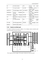
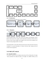
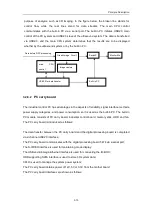
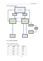
purpose of analysis, such as 3D imaging. In the figure below, the broken line stands for
control flow, while the real lines stand for data streams. The main CPU control
communicates with the built-in PC via a serial port. The built-in PC initiates USB2.0 main
control of the PC system and USB2.0 slave of the ultrasound system. The data is transferred
via USB2.0, and the main CPU system determines that the results are to be displayed
whether by the ultrasound system or by the built-in PC.
3.2.8.2
PC carry board
The industrial control PC has advantages in the aspects of reliability, signal interface methods,
power supply categories, and power consumption, so it is used as the built-in PC. The built-in
PC module consists of PC carry board, industrial control board, memory stick, HDD and fan.
The PC carry board is introduced as follows:
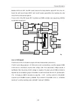
The data transfer between the PC carry board and the digital processing board is completed
via 2-channel USB2.0 interface;
The PC carry board communicates with the digital processing board 5474 via a serial port;
The S-VIDEO interface is used for maintaining mode display;
The USB and kilomega Ethernet interface is used for connecting the IO-BOX;
HDD supporting SATA interface is used to store 3D system data;
CPLD is used to manage the system power system;
The PC carry board obtains power of 12V, 5V or 3.3V from the mother board;
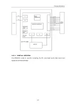
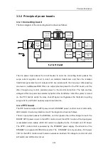
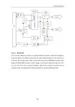
The PC carry board interfaces are shown as follows:
Graph/image Circuit
Built-in PC
Image capture
USB2.0 for data transfer
main
CPU
control
Data before DSC processing
MonitorMo
SwitchS
Содержание DC-6
Страница 1: ...DC 6 DC 6T DC 6Vet Diagnostic Ultrasound System Service Manual...
Страница 2: ......
Страница 20: ...2 1 2 System Overview 2 1 System Appearance 2 1 1 Complete System with CRT Monitor...
Страница 23: ...System Overview 2 4 2 2 LCD Monitor...
Страница 26: ...System Overview 2 7 2 2 3 Lever of upper support arm...
Страница 66: ...4 1 4 System Structure and Assembly Disassembly 4 1 Exploded View of Complete System...
Страница 97: ...System Structure and Assembly Disassembly 4 32 10 screw caps 13 M4 8 screws Rear cover assembly...
Страница 101: ...System Structure and Assembly Disassembly 4 36 Power boards Card detacher...
Страница 138: ...Checks 6 4 6 3 Safety Checks 6 3 1 Electric safety Refer to Appendix D Electrical Safety Inspection...
Страница 187: ...D 13 ELECTRICAL SAFETY INSPECTION 7 Mains on Applied Part Leakage LIMITS For BF ECG Input and transducer 5000 A...
Страница 191: ...P N 2105 20 40473 V10 0...

