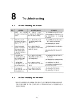
Troubleshooting
8-2
No.
problem
possible reason
measure
1
There is no display on the
monitor.
The monitor indicator isn’t
on.
Due to fault of the
monitor power.
Check the power cable.
2
There is no display on the
monitor.
The monitor indicator is in
yellow color.
Due to fault of the
monitor signal.
1. Check the signal cable.
2. Check connection of the IO
BOX.
3
There is no display on the
monitor.
The monitor indicator is in
green color.
Due to fault of setup
or DSP board.
1
.
Check the contrast and
brightness knobs.
2
.
Replace the DSP board.
4
The image is abnormal.
Due to fault of the
monitor signal.
Check the signal cable.
5
The screen flickers.
Due to fault of the
monitor signal or
CRT.
1. Check the signal cable.
2. Replace CRT.
8.3
Troubleshooting for the Power-up Process
No.
problem
possible reason
measure
1
The power-up graphic
isn’t displayed, and
there is no response
from the system.
1. Due to fault of the DSP
board.
2. Due to fault of the
IOBOX.
1. Replace the DSP board.
2. Replace IOBOX.
2
After the power-up
graphic is displayed,
there is no response
from the system.
1. Due to fault of hard disk
drive.
2. Due to fault of the DSP
board.
1. Check the HDD cable,
and remove the HDD to
rewrite data.
2. Replace the DSP board.
3
After the menu is
normally displayed,
there is no response
from the system.
1. Due to fault of the
boards.
1. Replace the boards in
the order of DSP,
beamformer, and
transmission boards.
4
After the menu is
normally displayed, the
system prompts the
error of transducer ID
recognition.
1. Due to damage of the
transducer’s FLASH.
2. Due to the HDD without
corresponding
transducer data.
1. Replace the transducer.
2. Copy transducer data to
the HDD.
Содержание DC-6
Страница 1: ...DC 6 DC 6T DC 6Vet Diagnostic Ultrasound System Service Manual...
Страница 2: ......
Страница 20: ...2 1 2 System Overview 2 1 System Appearance 2 1 1 Complete System with CRT Monitor...
Страница 23: ...System Overview 2 4 2 2 LCD Monitor...
Страница 26: ...System Overview 2 7 2 2 3 Lever of upper support arm...
Страница 66: ...4 1 4 System Structure and Assembly Disassembly 4 1 Exploded View of Complete System...
Страница 97: ...System Structure and Assembly Disassembly 4 32 10 screw caps 13 M4 8 screws Rear cover assembly...
Страница 101: ...System Structure and Assembly Disassembly 4 36 Power boards Card detacher...
Страница 138: ...Checks 6 4 6 3 Safety Checks 6 3 1 Electric safety Refer to Appendix D Electrical Safety Inspection...
Страница 187: ...D 13 ELECTRICAL SAFETY INSPECTION 7 Mains on Applied Part Leakage LIMITS For BF ECG Input and transducer 5000 A...
Страница 191: ...P N 2105 20 40473 V10 0...


