Principle Description
3-4
The amplifier board consists of high-voltage isolation circuit, channel select circuit, primary
voltage-controlled gain amplification circuit and secondary fixed gain amplification circuit. The
control signal of the channel select logic is derived from the beamformer board, and this
signal controls the on-off of the reception channel. The primary gain amplification circuit
consists of AD8332 and the peripheral circuits. The AD8332 is a dual-channel
voltage-controlled gain amplifier, and the gain voltage is derived from DA conversion from the
beamformer board and ranges between 0.04V and 1V. The secondary fixed gain amplification
circuit consists of AD8132 and the peripheral circuits.
3.2.4 Beamformer board
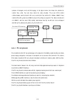
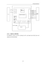
The block diagram of the beamformer board is shown as follows:
The beamformer board consists of beamformer module, signal processing FPGA module, and
signal processing DSP module. The beamformer board is designed for AD sampling,
beamforming, radio frequency signal processing, Doppler signal processing, flow signal
processing, video signal processing, and generation of scan control signal, etc.
The channel difference analog signal, transmitted from the system motherboard, passes the
low-pass filter to avoid aliasing of subsequent AD sampling. The cut-off frequency is 15 MHz.
After the signal is filtered and passes 8 pieces of high-speed AD for sampling, the sampled
data is sent to FPGA U46 and U65 for beamforming.
The data, after beamforming, is sent to FPGA U4 for B/W signal processing.
Содержание DC-6
Страница 1: ...DC 6 DC 6T DC 6Vet Diagnostic Ultrasound System Service Manual...
Страница 2: ......
Страница 20: ...2 1 2 System Overview 2 1 System Appearance 2 1 1 Complete System with CRT Monitor...
Страница 23: ...System Overview 2 4 2 2 LCD Monitor...
Страница 26: ...System Overview 2 7 2 2 3 Lever of upper support arm...
Страница 66: ...4 1 4 System Structure and Assembly Disassembly 4 1 Exploded View of Complete System...
Страница 97: ...System Structure and Assembly Disassembly 4 32 10 screw caps 13 M4 8 screws Rear cover assembly...
Страница 101: ...System Structure and Assembly Disassembly 4 36 Power boards Card detacher...
Страница 138: ...Checks 6 4 6 3 Safety Checks 6 3 1 Electric safety Refer to Appendix D Electrical Safety Inspection...
Страница 187: ...D 13 ELECTRICAL SAFETY INSPECTION 7 Mains on Applied Part Leakage LIMITS For BF ECG Input and transducer 5000 A...
Страница 191: ...P N 2105 20 40473 V10 0...


