Principle Description
3-22
3.3.2 Principle of power boards
3.3.2.1
Connecting board
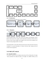
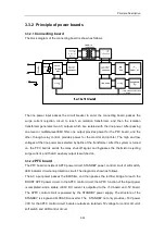
The block diagram of the connecting board is shown as follows.
The line power input passes the circuit breaker to enter the connecting board, passes the
surge current rejection circuit to reach an isolation transformer, and then the isolation
transformer generates two AC outputs which are isolated with the line power. After passing
one-level or multiple-level EMI filter, one output provides power for the PFC board, and the
other, through relay control, provides power for the monitor and printer. The high and low
voltages of the line power are selected by tieline of the transformer. After the system is turned
on, the PFC boards sends the relay shut-off signal, and bypasses the thermistor rejecting
surge current, and the AC auxiliary output is switched on.
3.3.2.2
PFC board
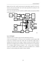
The PFC board consists of APFC power circuit, STANDBY power, control circuit of soft switch,
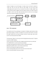
LED indicator circuit and protection circuit. The diagram is shown as follows.
The AC input power passes the EMI filter, and then passes the rectifier bridge to reach the
BOOST APFC power circuit. In the APFC control circuit, the APFC function of the input power
is completed, and a stable +390V DC current is outputted to the +5V board and -5V board.
The APFC control circuit is powered by the STANDBY power supply. The structure of the
STANDBY is single-end FLYBACK converter. The STANDBY not only pr18V power
VCC for the APFC control circuit, but also outputs an is5V voltage for control circuit of
soft switch and LED control circuit.
Содержание DC-6
Страница 1: ...DC 6 DC 6T DC 6Vet Diagnostic Ultrasound System Service Manual...
Страница 2: ......
Страница 20: ...2 1 2 System Overview 2 1 System Appearance 2 1 1 Complete System with CRT Monitor...
Страница 23: ...System Overview 2 4 2 2 LCD Monitor...
Страница 26: ...System Overview 2 7 2 2 3 Lever of upper support arm...
Страница 66: ...4 1 4 System Structure and Assembly Disassembly 4 1 Exploded View of Complete System...
Страница 97: ...System Structure and Assembly Disassembly 4 32 10 screw caps 13 M4 8 screws Rear cover assembly...
Страница 101: ...System Structure and Assembly Disassembly 4 36 Power boards Card detacher...
Страница 138: ...Checks 6 4 6 3 Safety Checks 6 3 1 Electric safety Refer to Appendix D Electrical Safety Inspection...
Страница 187: ...D 13 ELECTRICAL SAFETY INSPECTION 7 Mains on Applied Part Leakage LIMITS For BF ECG Input and transducer 5000 A...
Страница 191: ...P N 2105 20 40473 V10 0...


