Principle Description
3-15
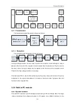
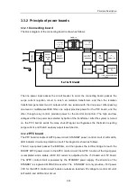
5V/3.3V
DC/DC
converter
TGC
adjustment (8-
segment)
enclosure
protective
earth
serial
comm
interface
ATmega64L
LED drive/control
74HC373
buzzer
EPM570T144
DC/DC
converter
rotary encoder
74HC14
65-key matrix
rotary encoder
knob value
RS232
serial
level
converter
4 independent
keys
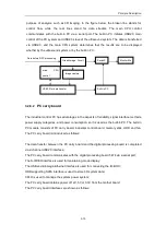
The keyboard plays an important role in information communication between the ultrasound
system and environment, and on the basis of functions it consists of: CPU circuit, DC/DC
conversion circuit, key control circuit, trackball control circuit, encoder control circuit, LED
drive circuit and STC A/D sampling circuit. The CPU circuit consists of one MCU chip and the
peripheral circuit, and it is the core of the keyboard, to process various types of information.
The DC/DC circuit is used to provide different levels required by the keyboard. The key
control circuit refers to the key processing hardware, which consists of CPLD and the
peripheral circuit. The trackball control circuit and encoder control circuit are used to convert
the external mechanical actions to signals which are recognizable by MCU, and the circuits
consist of trackball, encoder, waveform shaping circuit and hardware processing circuit. The
LED control circuit is used to indicate statuses of LEDs. The STC A/D sampling circuit
consists of sliding potentiometer, amplifier and AD sampling circuit, and it is used to convert
the analog signal from the sliding potentiometer to the digital signal which can be accepted by
MCU.
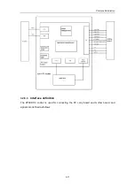
3.2.12 Detection board of Power Output
The detection board of power output is designed to precisely adjust the programmable
high-voltage and monitor other output voltage.
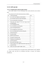
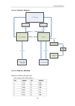
The programmable high-voltage is divided into PHV1, -PHV1, PHV2 and -PHV2, and the
adjustment ranges are between +5V and +80V and between -5V and -80V, and the
adjustment precision is 1
%
.
For other voltages, the digital voltages include: D+12V, D+5V, D+3.3V and D-12V; the analog
voltages include: A+100V, A-100V, A+12V, A+5V and A-5V.
Содержание DC-6
Страница 1: ...DC 6 DC 6T DC 6Vet Diagnostic Ultrasound System Service Manual...
Страница 2: ......
Страница 20: ...2 1 2 System Overview 2 1 System Appearance 2 1 1 Complete System with CRT Monitor...
Страница 23: ...System Overview 2 4 2 2 LCD Monitor...
Страница 26: ...System Overview 2 7 2 2 3 Lever of upper support arm...
Страница 66: ...4 1 4 System Structure and Assembly Disassembly 4 1 Exploded View of Complete System...
Страница 97: ...System Structure and Assembly Disassembly 4 32 10 screw caps 13 M4 8 screws Rear cover assembly...
Страница 101: ...System Structure and Assembly Disassembly 4 36 Power boards Card detacher...
Страница 138: ...Checks 6 4 6 3 Safety Checks 6 3 1 Electric safety Refer to Appendix D Electrical Safety Inspection...
Страница 187: ...D 13 ELECTRICAL SAFETY INSPECTION 7 Mains on Applied Part Leakage LIMITS For BF ECG Input and transducer 5000 A...
Страница 191: ...P N 2105 20 40473 V10 0...

